35
SA*\Pi-£
tr*
fcAfOOfA
»TEP
vc»uTAOK OvrrpuT
WAvfc
jnput
SAMPLE
COMMA*
INPUT
OOTptfT
.AWTDarr
iMpuT
tDMMANTp
Pyu&
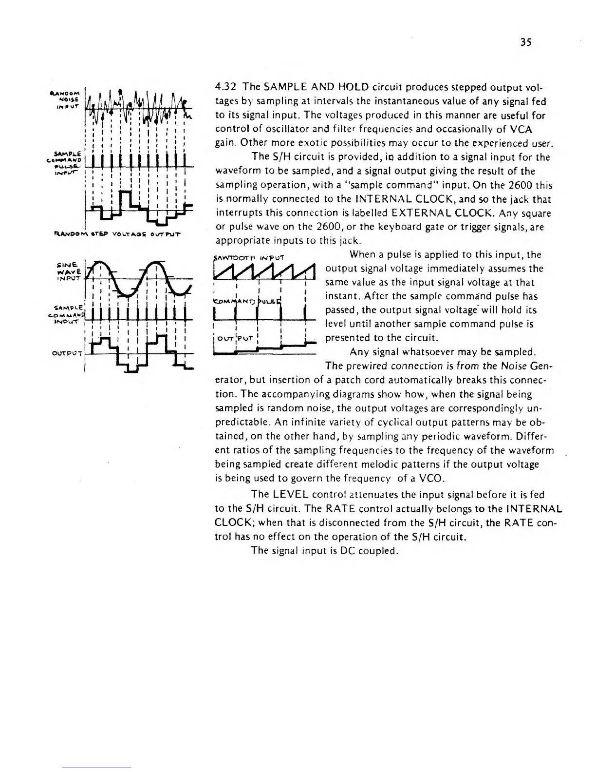
4.32 The
SAMPLE
AND
HOLD circuit produces stepped
output
vol-
tages
by sampling at intervals
the
instantaneous value
of any
signal fed
to
its
signal
input.
The
voltages produced in this manner
are
useful for
control
of
oscillator and
filter
frequencies
and
occasionally
of
VCA
gain. Other
more exotic
possibilities may
occur
to the
experienced
user.
The
S/H circuit
is
provided,
io
addition to
a
signal
input for
the
waveform
to.be sampled, and
a
signal output giving
the result
of the
sampling
operation, with a
"sample command" input.
On
the 2600 this
is normally
connected to
the
INTERNAL
CLOCK,
and
so the
jack that
interrupts
this connection is labelled EXTERNAL
CLOCK.
Any square
or pulse wave
on
the
2600,
or
the
keyboard
gate or trigger
signals, are
appropriate
inputs
to this jack.
When a
pulse
is applied to this
input, the
output signal
voltage
immediately
assumes the
same
value as the input signal voltage
at that
instant.
After
the sample
command pulse
has
passed, the output signal vo!tage~will
hold its
level
until another
sample command pulse is
presented
to the circuit.
Any signal
whatsoever
may be sampled.
The
prewired
connection
is
from
the Noise
Gen-
erator,
but insertion of
a patch cord automatically breaks
this connec-
tion. The
accompanying diagrams
show
how,
when
the
signal being
sampled is random noise,
the output voltages are correspondingly un-
predictable.
An infinite
variety of cyclical output
patterns
may be
ob-
tained, on
the other
hand,
by sampling any periodic waveform. Differ-
ent ratios
of
the
sampling
frequencies
to
the frequency
of
the waveform
being
sampled create different
melodic patterns if the output
voltage
is being used
to govern
the
frequency
of
a VCO.
The
LEVEL control
attenuates the
input
signal before
it is
fed
to the S/H
circuit.
The RATE
control
actually belongs to the
INTERNAL
CLOCK; when that is
disconnected from the
S/H circuit, the RATE con-
trol
has
no
effect on the
operation of the
S/H
circuit.
The signal input
is DC coupled.