40
jng
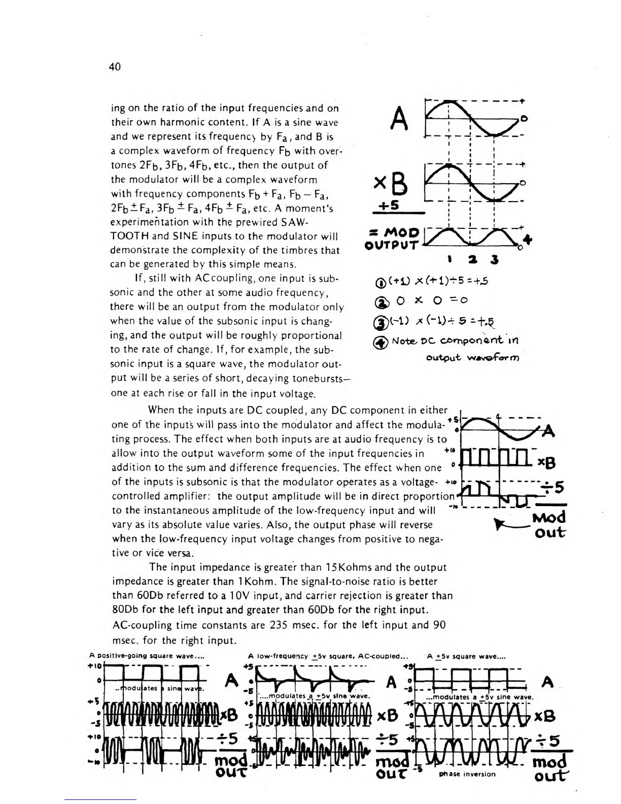
on the ratio of the
input frequencies
and
on
their own harmonic content. If
A
is
a sine wave
and
we represent its frequency
by
F
a
,and
B
is
a
complex waveform of frequency
F
D
with
over-
tones
2Ffc>,
3Ffc>,
4F
D
,
etc.,
then the output
of
the
modulator
will
be
a complex waveform
with frequency components
Fb
+
F
a>
Fb
—
F
a
,
2Fb±F
a
,
SFb^-
F
a
,4Fb
±
F
a
,
etc. A moment's
experimentation with
the prewired
SAW-
TOOTH and
SINE
inputs
to the
modulator
will
demonstrate the complexity of
the timbres
that
can
be
generated by this simple
means.
If,
still with
ACcoupling,
one input
is
sub-
sonic
and the other at some
audio
frequency,
there
will be an output from
the modulator
only
when
the value of
the
subsonic input is
chang-
ing,
and
the output will be roughly
proportional
to
the rate of change. If,
for example, the
sub-
sonic input
is
a
square wave,
the modulator
out-
put
will
be a series of
short, decaying
tonebursts-
one
at each
rise or fall
in the input voltage.
s
MOO
OUTPUT
«
a
3
(£>
O
x
o
=
o
(2p)
Mote.
PC
cornporj^nt
in
Output WAv^Form
When
the inputs are
DC
coupled, any
DC
component
in
either
•Hi
one of the
inputs
will
pass into the modulator and
affect
the moduia-
4
^
A
ting
process. The
effect
when
both inputs are at
audio frequency
is to
allow
into the output waveform
some
of
the input frequencies in
addition
to the
sum
and
difference frequencies. The effect when one
of the
inputs is subsonic
is that the
modulator operates
as
a
voltage-
+»o
\^
controlled
amplifier: the
output
amplitude will be in direct proportion
to
the
instantaneous amplitude of the low-frequency input
and
will
~*
vary
as its absolute value
varies. Also,
the
output
phase
will reverse
when
the low-frequency
input
voltage
changes from positive to nega-
tive
or
vice
versa.
The
input impedance
is
greater than
15Kohms and the output
impedance
is greater than
1 Kohm.
The signal-to-noise
ratio is
better
than 60Db referred
to
a 1 0V
input, and carrier rejection
is
greater than
80Db for
the left input
and
greater than
60Db
for the right input.
AC-coupling time constants are 235
msec, for
the left
input and 90
msec, for
the right input.
out
A
positive-going square
wave....
10
A
iow-frequertcy +
5v
square, AC-coupled...
A +5v square wave....
A.;-
A
...modulates
a
+5v sine wave.
OUT
our
phase
inversion
OLff