30
erned input
for
controlof pulse
width; it
is
labelled
PULSE WIDTH
MODULATION.
The
Noise Generator output
is
prewired
to
this input.
4.1
1
3
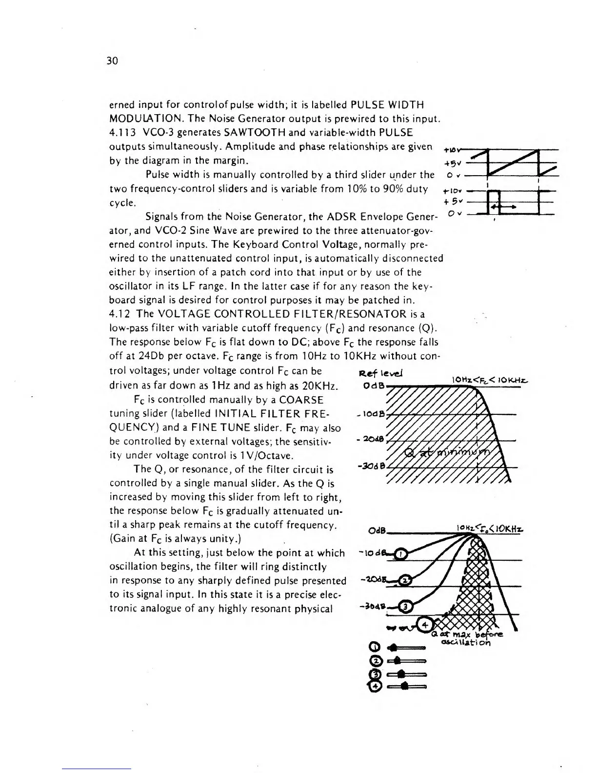
VCO-3 generates
SAWTOOTH and variable-width PULSE
i
outputs
simultaneously.
Amplitude and phase relationships are given
by
the
diagram in the margin.
Pulse
width
is
manually
controlled
by
a
third slider under the
two
frequency-control sliders
and is variable from
10%
to 90% duty
cycle.
Signals from the
Noise Generator, the
ADSR
Envelope
Gener-
ator, and VCO-2 Sine Wave
are prewired
to
the three attenuator-gov-
erned
control inputs. The
Keyboard Control
Voltage, normally
pre-
wired to the unattenuated
control input,
is
automatically disconnected
either
by
insertion of
a patch cord into that
input
or
by
use of the
oscillator
in
its
LF
range.
In the latter case if for any reason
the key-
board signal
is
desired for
control purposes it may be patched in.
4.12 The VOLTAGE
CONTROLLED FILTER/RESONATOR is
a
low-pass
filter
with variable cutoff frequency
(F
c
)
and resonance
(Q).
The
response below
F
c
is
flat down
to
DC;
above
F
c
the response fails
off
at
24Db per octave.
F
c
range is from
10Hz to
lOKHz without
con-
O
v ^s
trol
voltages;
under
voltage
control
Fc
can
be
driven as far
down
as 1
Hz
and
as
high
as
20KHz.
F
c
is controlled manually
by a
COARSE
tuning slider
(labelled
INITIAL FILTER
FRE-
QUENCY) and
a FINE TUNE
slider.
F
c
may
also
be controlled
by
externa!
voltages;
the sensitiv-
ity under voltage
control is 1 V/Octave.
The
Q,
or resonance, of
the filter
circuit
is
controlled
by
a single manual
slider.
As the
Q
is
increased
by
moving this
slider from
left
to right,
the response
below
F
c
is
gradually
attenuated
un-
til
a sharp peak remains
at the
cutoff
frequency.
(Gain
at
F
c
is always unity.)
Ref
levd
OdB
tOHz<R<
JOlCHr.
^lOdfi
-
2Cd&
-3Cd$
OdB
l°Hz.<rX
\OKHr~
At
this setting,
just below the point
at which
-tod
oscillation
begins,
the filter
will ring distinctly
in response
to
any
sharply
defined
pulse presented
to its
signal input.
In this state
it is a precise
elec-
tronic
analogue of any
highly resonant
physical
-706
-304*
o*ci
Uati
on