33
ADStK
OUTPUT
*ust»\n l#**l
GATE,
\N90T
way
damaged
by
such
operation
(a
voltage is a
voltage is a
voltage), but
it is the exception and not the
rule. They are therefore
grouped here
as CONTROL-SIGNAL
GENERATORS.
4.31 The two ENVELOPE GENERATORS
produce
transient wave-
forms with controllable rise and fall times,
and are
used primarily with
the VCF and
FCA in
generating
events whose fluctuating
harmonic
and
amplitude
characteristics
must
be accurately
and
repeatably controlled.
Note
that the
output from both
generators is
in itself
merely
a positive-
going voltage whose
rise and
fall time is
governed
by
the
slide controls
on the
generator
itself
and
whose onset and overall duration is
gov-
erned in turn
by a GATE
voltage which
controls the
generator.
The
maximum
value that
either envelope can reach is +10V;
thus,
unattenuated, either envelope is capable
of
driving a VCF or
VCA
from its minimum
initial
setting
(10Hz for the VCF,
—lOODb for
the VCA)
all
the way
up
to maximum.
See
4.1 2
and
4.13,
specifically
the
data
on control input sensitivity. Reread too
sections
2.1
6_through
2.17.
GATES for the operation
of the envelope
generators
may
be
provided
by
a MANUAL START button, the
3604 keyboard
controller,
or any +10V square-wave or pulse signal
presented to the
external input
indicated
by
the panel graphics.
The two
latter sources
are switch-
selected
by
the slide switch just
under the lower
(A/R)
generator. The
MANUAL START button overrides both
of
these.
The
output
impedance of both
generators is
1
Kohm.
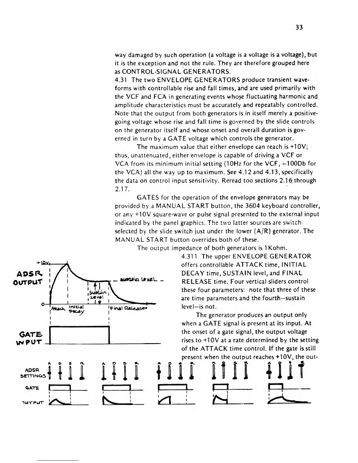
4.311 The upper
ENVELOPE
GENERATOR
offers controllable
ATTACK
time,
INITIAL
DECAY
time, SUSTAIN
level,
and FINAL
RELEASE
time. Four vertical
sliders control
these
four
parameters: note that
three of these
are time parameters
and the fourth—
sustain
level—is not.
The
generator produces an output
only
when
a GATE signal
is
present
at its
input. At
the onset of
a
gate signal,
the
output
voltage
rises
to
+10V at a
rate determined
by
the
setting
of the
ATTACK
time control. If the
gate is still
present
when
the output reaches
+10V, the out-
ADSR
*>ETT\NOS
*~
">u"rpwrr