C
hapter
Ⅲ
G
eneral
D
escriptions
for
F
unction
B
locks
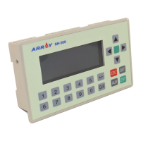
3.2.11 Tel (The Voice Module needs to be used in conjunction with FAB)
Figure Pin Description
Input
The following input ports are at choice: I1 ~ IC, Q1
~ Q8, HI, LO, M00 ~ M126, P0 ~ P9.
Output
When the output is 1, the telephone number of out-
put port will be dialed to output. If the input is kept
1 all the time, dialing repeats every 20 seconds and
when the input transforms to be 0, dialing stops.
The option range of the output port should not ex-
ceed 25-digit telephone number.
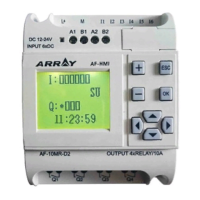
a. The basic circuit of periphery devices for controlling calling signals is shown
in the following diagram:
This control requires the presetting of the telephone two-tone signal (P0 ~ P9)
to drive RS relay during the programming of FAB. The periphery devices are
driven by the output of RS relay, so when FAB receives a P0 ~ P9 signal of a
calling, it is possible to control the peripheral devices.
37
Note:
The telephone blocks are mainly used to auto-dial for an alarm. If these
blocks are used together with a locked relay, the terminal equipment,
which not only receives calling signals but also dials to output an alarm,
should be made.