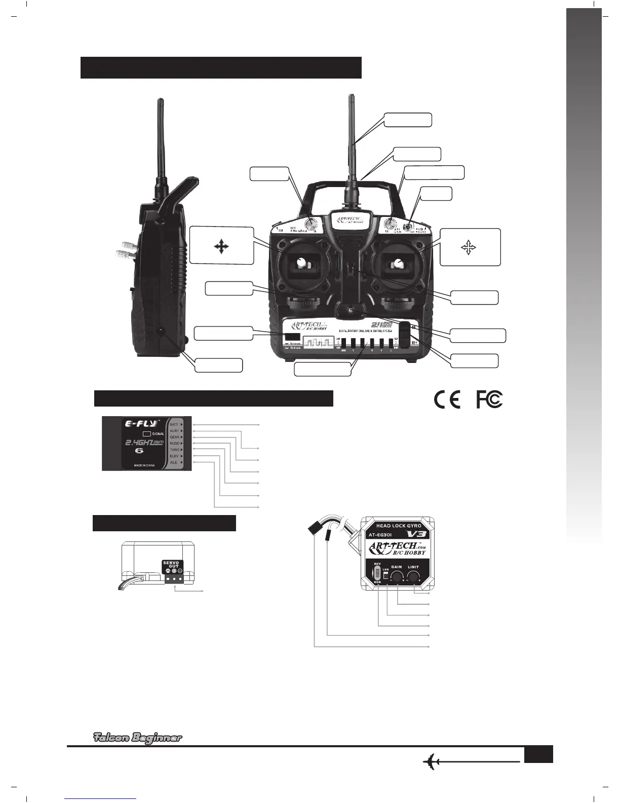
FUNCTIONS FOR CONTROL SET
PICTURE OF CONTROL SET CONNECTION
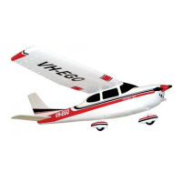
GYRO ADJUSTMENT
1. Connect to
tail servo
Elevator down
Rudder
left
Throttle Max
sweepback
adjustment trim switch
Dual Rate
(D/R) Switch
Charger port
Frequency Binding Switch
Servo reverse switch
Power switch
Power indicator
Hook
Handle
Antenna
Trim
Dual Rate(D/R)
Trim Switch
Rudder
right
Throttle up
Left
Aileron
Up
Right
Aileron
Up
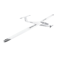
RECEIVER
ER61-2.4GHz
CH
Flapron
Landing gear
Rudder
Throttle
Elevator
Aileron
Power/
Frequency bind
www.art-tech.cn
9
MODE 2
Throttle Min
. Gy ro signal Co nnect to Ch 46
. Gyro gain Connect to Ch55
3 Connect to tail servo.
2 Gain adjustment.
1 Rudde r itinerar y adj ust ment .
4. Reverse switch for servo
Assembling Gyro :
Make sure radio control system and servos are in good working condition, and the servo arms are in right
position.
1.
2. Fix the gyro to the right place close to CG.