LIST OF FIGURES
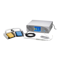
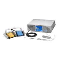
Figure 2 – 1 Layout of controls, indicators, and receptacles on the front panel..................2-2
Figure 2 – 2 Controls for setting and recalling presets........................................................2-4
Figure 2 – 3 Controls for the Cut and Blend modes............................................................2-5
Figure 2 – 4 Controls for the Coag mode ............................................................................2-6
Figure 2 – 5 Controls for the Bipolar mode .........................................................................2-7
Figure 2 – 6 Indicators for power, return electrodes, and footswitch control.......................2-8
Figure 2 – 7 Location of the unit power switch and front panel receptacles .......................2-9
Figure 2 – 8 Layout of connectors and controls on the rear panel....................................2-10
Figure 5 – 1 Fuse holder......................................................................................................5-2
Figure A – 1 Output power vs impedance for Cut I mode...................................................A-5
Figure A – 2 Output power vs impedance for Cut II mode..................................................A-5
Figure A – 3 Output power versus impedance for Blend mode, set at Minimum................A-6
Figure A – 4 Output power versus impedance for Blend mode, set at Maximum...............A-6
Figure A – 5 Output power vs impedance for Pinpoint mode..............................................A-7
Figure A – 6 Output power vs impedance for Spray mode .................................................A-7
Figure A – 7 Output power vs impedance for Bipolar mode ...............................................A-8
vi Arthrex, Inc.
 Loading...