2 Aruba 510 Series Campus Access Points | Installation Guide
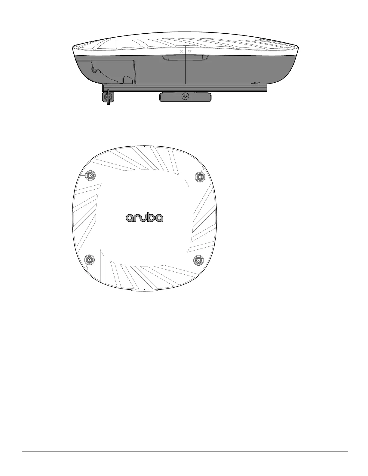
Figure 2 LEDs (AP-515 shown)
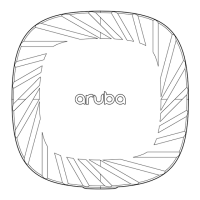
Figure 3 AP-514 Front View
External Antenna Connectors
The AP-514 access points are equipped with four external antenna connectors located on the front
corners of the access point (see
Figure 3). Antenna ports A0 and A1 (corresponding with radio chains 0
and 1), are used for both radios and bands (RF signals are diplexed), while antenna ports A2 and A3
(corresponding with radio chains 2 and 3) are used for the 5 GHz radio only.