TD 90227GB
10 October 2013 / Ver. D
System Installation
Ascom Paging System
9
• GP 4103 is a 26-47 MHz, dc-grounded ground-plane antenna for mounting on a mast.
The antenna must be ordered for the correct frequency. The antenna has a UHF type
connector.
• SAT-1 is a compact helix antenna about 1 metre long for the 27 MHz band that is often
used ind
oors because of its short length. The antenna has a UHF type connector. The
manufacturer recommends a few different coaxial cable lengths but the same low
standing wave ratio can be achieved by moving the antenna to different possible
mounting locations (standing-wave metre required).
• Another alternative is a two-band antenna for HF/UHF plus a duplex filter.
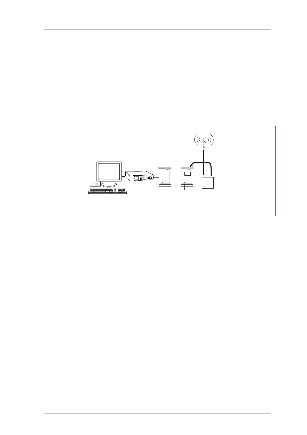
5.3 Tuning Circuits and Power Divider
MFJ-901B
Terminal
Transmitter
Central
Unit
Netpage
PC
Unite CM
Figure 6. Antenna tuner in HF system.
MFJ-901B, the antenna tuning unit for HF is connected between the transmitter and
ante
nna.
If an antenna cannot be installed in a
normal manner or if the coaxial cable has an
excessively high standing-wave ratio, the antenna tuner can be used to match the
transmitter impedance to the antenna (for example boat installations, culverts, or cellars).
Antenna transformer MAT-50 is used in HF installations at the output of the transmitters
to
provide galvanic isolation from the antenna and protection from over-voltage and
transients caused by lightning.
5.4 Antenna Location
An outdoor antenna should be located as centrally and unobstructed as possible within
the designed coverage area. The antenna must not be placed near metal-clad chimneys or
similar structures.
There are several alternatives:
• On the roof; provides good coverage around the building but usually provides
dimin
ished coverage within the building.
• On the ground floor; theoretically provides good coverage in the entire building but
may
result in uneven coverage due to absorption by floors and other building
structures.
• On the roof of a lower nearby building; provides good coverage of entire building if
th
e building is not too wide.
When planning an installation,
a coverage test from the intended antenna site should
always be carried out.

 Loading...
