TD 90227GB
10 October 2013 / Ver. D
System Installation
Ascom Paging System
5
.
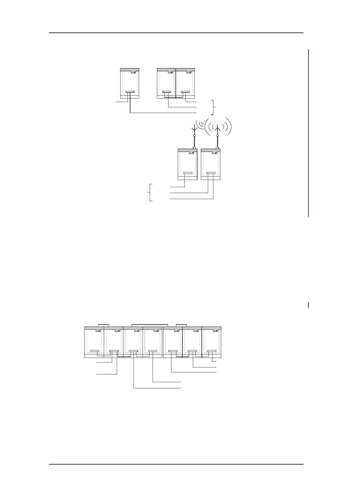
A-bus
R-line
FL-bus
D-bus
Central
Unit
Reference
Module
Receiver
Interface
to terminal site
R-line
FL-bus
D-bus
to central site
Fixed
Receiver
Terminal
Transmitter
Figure 2. System solution: 2-way data communication.
2.3 With Data Modem to Transmitters
Data modem introduces delay in the transmitter signal. Transmitter signals “in the air” will
differ and cause distortion in areas of overlapping coverage. A basic rule in planning an
installation is to delay the signals to transmitters equally.
The transmitter code on the D-bus is always generated by the Central Unit. Be sure that
the
same number of modem-pairs are used between the Central Unit and each Terminal
transmitter. Several Terminal transmitters can be connected to one Data modem if the
location is suitable. Synchronize the data modems for the D-bus, see the figure below:
Figure 3. Private lines with data modem.
Reference
Module
Control Synchronizing D-bus
Delayed buses
direct to terminal site
A-bus
D-bus
System bus to
other units
A-bus
D-bus
Buses via modem
at terminal site
R-line
D-bus
FL-bus
Central
Unit
Data
Modem
Data
Modem
Data
Modem
Data
Modem
Receiver
Interface
 Loading...

