TD 90227GB
10 October 2013 / Ver. D
System Installation
Ascom Paging System
6
3 Fixed Receivers
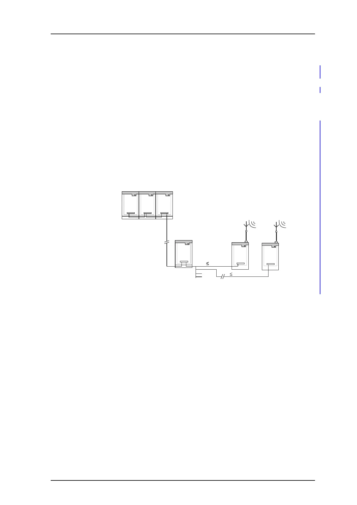
Fixed Receivers are connected to a Receiver Interface (RI), which in turn is connected to the
A-bus. Up to four receivers may be connected to the same RI, each with a separate
twisted-pair that must not exceed 1 km. Move the RI closer to the receivers if the distance
exceeds 1 km or use modems to extend the A-, B-bus of the RI.
Note that the twisted-pair (R-line) between each receiver and its interface is not included
in the
system modular bus and must therefore be connected separately, even when the
units are mounted together. When the Receiver is not activated, this line always carries a
quality tone of about 2.0 ± 0.2 Vp-p measured between L1 and L2.
When the Receiver is activated, the data
signal, a sinusoidal signal of about
5.0 ± 0.2 Vp-p, is superimposed on the quality to
ne. The quality tone can be generated at
four different frequencies corresponding to four quality levels.
The line is not polarized
A-bus
1 km
1 km
Receiver
Interface
Fixed
Receiver
Fixed
Receiver
Central Units
.
Figure 4. Receivers connected to the Centra
l Unit via the Receiver Interface.