Ascon Tecnologic - KM3 - L - ENGINEERING MANUAL - PAG. 12
When the EXCEED lamp is ON but PV is lower than SP, the
upper display will be in green value and it shows that the PV
is in the hysteresis area
Low limit control
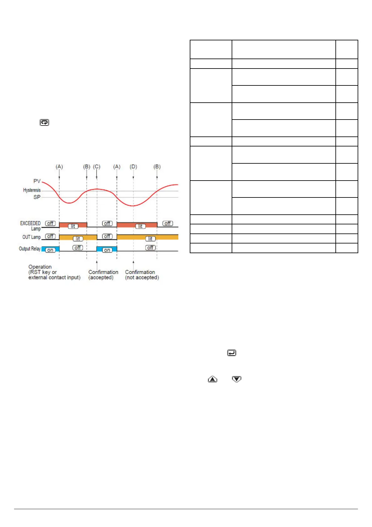
When a measured value (PV) exceeds a setpoint (SP),
“EXCEEDED” lamp (c) lights, and “OUT” lamp (b) turns ON .
The limit output relay is deenergizedthen. “EXCEEDED”
lamp turns off when PV goes into normal condition, while
the output (OUT) display lamp stays on as it is. The output
(OUT) display lamp turns off when a confi rming operation is
done by an operator.
The way to confi rm are:
pressing
key or by DI1 (according to the <<diS>>
parameter setting).
The confi rming operation is not accepted during PV exceeds
SP (D) (during EXCEEDED lamp lights*). State of output
relay is de-energized whenever “OUT” lamp is on.
When the EXCEED lamp is ON but PV is Higher than SP,
the upper display will be in green value and it shows that the
PV is in the hysteresis area.
6.1 ACCESS LEVELS AND SPECIFIC
PARAMETERS
The instrument is showing the “standard display”
This instrument is equipped with 3 different access levels:
Level 1 – Operator Mode.(not protected by password)
Level 2 – Operator modify parameter (protected by a
programmable password [default 20])
Level 3 – Confi guration parameters mode (protected by
programmable password [default 30])
• The operator area (Level 1) allows: confi rmation
action, to see and to reset the << tin >> parameter
(time duration of the last shutdown condition detected)
and to see and to reset the << Min/max >> (minimum
or maximum measured value during last shutdown
condition detected).
Note: NOTE: when a new shutdown condition is detected,
the instrument automatically reset << tin>> and <<
min/max >> parameters and start to memorize the
values related with the new shutdown condition only.
At the end of the shut down condition, <<tin>> and
<<min/max>> can be read and reset.
• The Level 2 area encompasses the following
parameters:
Parameter Description dec.
point
SP Shutdown set point
AL1L For High and Low alarm it is the
low limit of the AL1 1threshold
dP
- For band alarm, it is low alarm
threshold
dP
AL1H For hight or low alarm, it is the high
limit of AL1 threshold
dP
For band alarm, it is high alarm
threshold
dP
AL1 alarm 1 threshold dP
AL2L For High and Low alarm it is the
low limit of the AL2 threshold
dP
- For band alarm, it is low alarm 2
threshold
dP
AL2H For hight or low alarm, it is the high
limit of AL2 threshold
dP
For band alarm, it is high alarm 2
threshold
dP
AL2 Alarm 2 threshold dP
HYS Hysteresis of the shutdown control. dp
FiL Digital fi lter on the measured value
bS PV input bias
• The Level 3 area encompasses all confi guration
parameters. NOTE: All parameters of the Level 3 can
be seen but not modify using -181 password.
6.2 ENTER THE “OPERATOR MODIFY
PARAMETER”
The instrument is showing the “standard display”.
1. Press the
button for more than 3 seconds;
2. The upper display will show PASS while the lower display
will show 0;
3. By
and buttons set the value assigned to
[44] PAS2 (Level 2 password).
Notes: 1. The factory default password for confi guration
parameters is equal to 20.
2. All parameter modifi cation are protected by a
time out. If no button is pressed for more than
10 second the instrument comes automatically
back to the Standard display, the new value of the
last selected parameter is lost and the parameter
modifi cation procedure is closed.
When you desire to remove the time out (e.g.
for the fi rst confi guration of an instrument) you
can use a password equal to 1000 plus the
programmed password
(e.g. 1000 + 20 [default] = 1020).
It is always possible to manually End the
 Loading...


