Do you have a question about the Ascon tecnologic X5 Series and is the answer not in the manual?
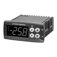
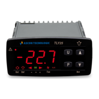
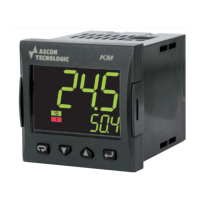
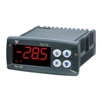
Overview of powerful features and broad functionalities of the X5 series controllers.
Details on how to understand and interpret the product's model code for identification.
Details on the controller's general description, dimensional details, and panel cut-out requirements.
Specifications for operating temperature, humidity, and altitude for optimal performance.
Step-by-step guide for inserting and securing the instrument into a panel mount.
Diagram and description of the terminal block connections for inputs and outputs.
Recommendations for routing cables to avoid interference and ensure signal integrity.
Illustrative wiring diagrams for specific applications like valve control.
Details on power supply requirements and various process variable (PV) input types.
Information on connecting auxiliary inputs and digital inputs for control functions.
Description and combinations of optional outputs for control, alarms, and retransmission.
Explains key functions and display behavior in operator and programming modes.
Details on parameter setting methods and the overall configuration procedure.
Configuration options for process variable inputs and target setpoints.
Settings for controller outputs and functions assigned to digital inputs.
Detailed setup for alarms, including types, thresholds, and behaviors.
Navigation and settings within Setpoint, Alarms, PID, Tuning, Input, Output, Serial Comm menus.
In-depth parameter explanations, access levels, password management, and calibration.
Description of the standard display modes and information shown to the operator.
How to access and modify parameters quickly through the Fast View function.
Commands executed via the keypad for setpoint modification, mode changes, and tuning.
How digital inputs can be used to command controller functions.
Overview of program structure, segments, and main characteristics of the setpoint programmer.
Details on maximum allowed deviation and program restart after power failure.
Settings for program number, status, segments, units, and cycles.
How to view the status of running programs, segments, and end conditions.
Methods for starting, stopping, holding, and resetting programs via keypad or digital inputs.
Specifications for PV input types, accuracy, auxiliary inputs, and digital inputs.
Parameters for PID, ON-OFF, and valve drive control modes.
Specifications for output types, alarms, setpoints, tuning, and communication.
Information on operational safety, power supply, EMC, and physical dimensions.
Information regarding the product warranty period and exclusions.
Table explaining the meaning of various icons used throughout the manual.
| Brand | Ascon tecnologic |
|---|---|
| Model | X5 Series |
| Category | Controller |
| Language | English |




 Loading...