13
3 - Electrical Connections
3.3.1 POWER SUPPLY
B
Switching power supply with mul-
tiple isolation and PTC protection.
• Standard version:
Nominal voltage:
100... 240Vac (-15...+10%);
Frequency 50/60Hz.
• Low Voltage version:
Nominal voltage:
24Vac (-25...+12%);
Frequency 50/60Hz
or 24Vdc (-15...+25%);
Power consumption 5W max.
L
N
25
26
PTC
included
Supply
27
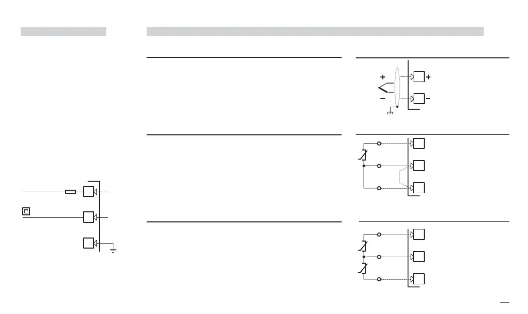
3.3.2 PV CONTROL INPUT
B
A L-J-K-S-R-T-B-N-E-W thermocouple type
• Connect the wires with the polarity as shown;
• Use always compensation cable of the correct type
for the thermocouple used;
• The shield, if present, must be connected to a prop-
er earth.
B For Pt100 resistance thermometer
• If a 3 wires system is used, use always cables of the
same diameter (1mm
2
min.), maximum line resistance
20 Ω/line.
• When using a 2 wires system, use always cables of the
same section (1.5mm
2
min.) and put a jumper between
terminals 11 and 12
C For ∆T (2x RTD Pt100) Special
A When the distance between the controller and the
sensor is 15m using a cable of 1.5mm
2
section, pro-
duces an error on the measure of 1°C.
R1 + R2 must be <320Ω
Wire resistance
150Ω max.
Only for two wires sys-
tem, put a jumper
between terminals 11
and 12.
Use wires of the same
length and 1.5 mm
2
size.
Maximum line resis-
tance 20 Ω/line.
x5-uk-ed5 17-09-2009 14:53 Pagina 13
 Loading...


