EasyManua.ls Logo

Ascon tecnologic TLY25 User Manual

Ascon tecnologic TLY25
11 pages
To Next Page IconTo Next Page
Page #1 background imageLoading...
Page #1 background image
FOREWORD
INDEX
1 INSTRUMENT DESCRIPTION
1.1 GENERAL DESCRIPTION
1.2 FRONT PANEL DESCRIPTION
2 PROGRAMMING
2.1 PROGRAMMING OF SET POINT
2.2 PARAMETERS PROGRAMMING
2.3 PARAMETER PROTECTION USING THE PASSWORD
2.4 PARAMETERS PROGRAMMING LEVEL
2.5 ACTIVE SET POINT SELECTION
2.6 ON / STAND-BY FUNCTION
2.7 CLOCK PROGRAMMING
3 INFORMATION ON INSTALLATION AND USE
3.1 PERMITTED USE
3.2 MECHANICAL MOUNTING
3.3 ELECTRICAL CONNECTIONS
3.4 ELECTRICAL WIRING DIAGRAM
4 FUNCTIONS
4.1 MEASURING AND VISUALIZATION
4.2 OUTPUTS CONFIGURATION
4.3 TEMPERATURE CONTROL
4.4 CONTINUOUS CYCLE FUNCTION
4.5 COMPRESSOR PROTECTION FUNCTION AND DELAY
AT POWER-ON
4.6 DEFROST CONTROL
4.7 MANUAL DEFROST
4.8 EVAPORATOR FANS CONTROL
4.9 ALARM FUNCTIONS
4.9.1 TEMPERATURE ALARMS
4.9.2 EXTERNAL ALARM
4.9.3 OPEN DOOR ALARM
4.9.4 ALARM MEMORY
4.10 DIGITAL INPUT
4.11 AUXILIARY OUTPUT
4.12 FUNCTION OF KEYS “U” AND “DOWN/AUX”
4.13 PARAMETERS CONFIGURATION BY A01
5 PROGRAMMABLE PARAMETERS TABLE
6
PROBLEMS , MAINTENANCE AND WARRANTY
6.1 SIGNALLING
6.2 CLEANING
6.3
WARRANTY AND REPAIRS
7 TECHNICAL DATA
7.1 ELECTRICAL DATA
7.2 MECHANICAL DATA
7.3 MECHANICAL DIMENSIONS, PANEL CUT-OUT AND
MOUNTING
7.4 FUNCTIONAL DATA
7.5 INSTRUMENT ORDERING CODE
1 - INSTRUMENT DESCRIPTION
1.1 - GENERAL DESCRIPTION
The model TLY 25 is a digital controller with microprocessor that is
typically used in cooling applications that have temperature control
with ON/OFF regulation and defrosting control with set time and
hours intervals (Real Time Clock Defrosting) by means of electrical
heating or hot gas/cycle inversion.
The instrument has 4 relay outputs, two inputs for PTC or NTC
temperature probes and a digital input, that can all be configured.
The 4 outputs can be used for controlling the compressor or the
temperature control device (OUT), the defrosting device (DEF), the
evaporation fan (FAN), an alarm (AL) or, alternatively any of the
previous functions, using an auxiliary device (AUX).
The two inputs for the PTC and NTC temperature probes (which
can be selected by parameter) can be used to measure the cell
temperature (Pr1) and the evaporator temperature (Pr2) while the
digital input (DIG) can be programmed to carry out various
functions such as defrosting commands, selecting a different set of
temperature regulations, external alarm signals, activating a
continuous cycle, and activating an auxiliary output etc.
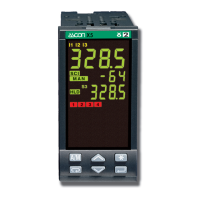
The instrument is equipped with 4 programme keys, a 4-digit
display and 9 LED signals.
Ascon Tecnologic - TLY25 - OPERATING INSTRUCTIONS - PAG. 1
MICROPROCESSOR-BASED
DIGITAL ELECTRONIC FREEZER
CONTROLLER
TLY25
This manual contains the information
necessary for the correct installation, and the
instructions for the use and maintenance of the
product; the user is advised to read it carefully
and conserve it for reference.
This publication is exclusive property of Ascon Tecnologic S.r.l.;
unless expressly authorized, reproduction and disclosure of
even part of its contents is strictly prohibited.
Ascon Tecnologic S.r.l. reserves the right to make visual
and functional modifications to this manual at any moment
and without advance warning.
In the event that a fault or malfunction of the device should
create hazardous or damaging situations for persons, property
or animals, note that the system must be fitted with additional
devices aimed at guaranteeing safety.
Ascon Tecnologic S.r.l. and its legal representatives shall
accept no responsibility for any damage caused to persons,
property or animals deriving from tampering, improper or
erroneous usage, or use that is not in conformity with the
specifications of the appliance.
OPERATING INSTRUCTIONS
17/06 - Code: ISTR_M_TLY25_e_02_--
ASCON TECNOLOGIC S.r.l.
Viale Indipendenza 56
27029 Vigevano (PV) ITALY
TEL.: +39 0381 69871 - FAX: +39 0381 698730
http:\\www.ascontecnologic.com
e-mail: info@ascontecnologic.com
Question and Answer IconNeed help?

Do you have a question about the Ascon tecnologic TLY25 and is the answer not in the manual?

Ascon tecnologic TLY25 Specifications

General IconGeneral
BrandAscon tecnologic
ModelTLY25
CategoryController
LanguageEnglish

Summary

1 INSTRUMENT DESCRIPTION

1.1 GENERAL DESCRIPTION

Provides an overview of the TLY 25 digital controller for cooling applications, detailing its functions and capabilities.

1.2 FRONT PANEL DESCRIPTION

Details the layout and components of the instrument's front panel, including keys, display, and LEDs.

2 PROGRAMMING

2.1 PROGRAMMING OF THE SET POINT

Explains how to set and adjust the desired temperature set points (SP1, SP2) for the controller.

2.2 PARAMETERS PROGRAMMING

Guides users through accessing and modifying various operational parameters via key presses and display.

2.3 PARAMETER PROTECTION USING THE PASSWORD

Describes how to set and use a password to protect parameter settings from unauthorized changes.

2.4 PARAMETERS PROGRAMMING LEVELS

Outlines the two levels of parameter access, visible and hidden, and how to switch between them.

3 INFORMATION ON INSTALLATION AND USE

3.1 PERMITTED USE

Specifies the intended use of the instrument according to safety standards and general application guidelines.

3.2 MECHANICAL MOUNTING

Provides instructions for physically installing the instrument into a panel, including hole dimensions and gasket use.

3.3 ELECTRICAL CONNECTIONS

Details how to safely and correctly connect the electrical wiring to the instrument's terminals.

3.4 ELECTRICAL WIRING DIAGRAM

Presents a visual diagram illustrating the correct electrical connections for the instrument's inputs and outputs.

4 FUNCTIONS

4.1 MEASURING AND VISUALIZATION

Explains how to select probe types, units, resolution, and view various measurements on the display.

4.2 OUTPUTS CONFIGURATION

Details how to configure the instrument's four relay outputs for different functions like compressor, defrost, or fans.

4.3 TEMPERATURE CONTROL

Describes the ON/OFF temperature regulation mode, including set points, differentials, and cooling/heating modes.

4.4 CONTINUOUS CYCLE FUNCTION

Explains the function that maintains a configured output active for a set time, overriding temperature control.

4.5 COMPRESSOR PROTECTION FUNCTION AND DELAY AT POWER-ON

Covers features designed to protect the compressor by preventing short cycling and managing start-up delays.

4.6 DEFROST CONTROL

Details the configuration of automatic and manual defrost cycles, including types and timing.

4.7 MANUAL DEFROST

Describes the procedure for manually initiating a defrost cycle using a front panel key.

4.8 EVAPORATOR FANS CONTROL

Explains how to configure and manage the evaporator fan operation based on various conditions.

4.9 ALARM FUNCTIONS

Covers the instrument's alarm capabilities, including types, enablement, and silencing.

4.9.1 TEMPERATURE ALARMS

Details the configuration of high and low temperature alarms, including thresholds and differentials.

4.9.2 EXTERNAL ALARM

Explains how to configure and manage external alarm signals detected via digital input.

4.9.3 OPEN DOOR ALARM

Describes the function for detecting and signaling an open door condition, often linked to fan or compressor control.

4.9.4 ALARM MEMORY

Explains how to enable and manage the memory function for alarms, allowing them to be recalled after they have ceased.

4.10 DIGITAL INPUT

Details the configuration and functions of the digital input, allowing external control signals.

4.11 AUXILIARY OUTPUT

Explains how to configure and use an auxiliary output for additional control functions.

4.12 FUNCTION OF KEYS "U" AND "DOWN/AUX"

Describes how the 'U' and 'DOWN/AUX' keys can be assigned custom functions beyond their default operations.

4.13 PARAMETERS CONFIGURATION BY "A01"

Explains the use of the A01 device for transferring and copying parameter configurations between instruments.

5 PROGRAMMABLE PARAMETERS TABLE

6 PROBLEMS, MAINTENANCE AND WARRANTY

6.1 SIGNALLING

Describes error codes, their reasons, and the corresponding actions for troubleshooting.

6.2 CLEANING

Provides recommendations for cleaning the instrument safely and effectively.

6.3 WARRANTY AND REPAIRS

Outlines the warranty period, terms, and procedures for repairs or replacements.

7 TECHNICAL DATA

7.1 ELECTRICAL DATA

Lists the electrical specifications of the instrument, including power supply, consumption, and I/O ratings.

7.2 MECHANICAL DATA

Provides mechanical specifications such as housing dimensions, weight, and mounting details.

7.3 MECHANICAL DIMENSIONS, PANEL CUT-OUT AND MOUNTING

Details the physical dimensions, panel cut-out size, and mounting methods for installation.

7.4 FUNCTIONAL FEATURES

Summarizes the main functional capabilities and specifications like measurement range and accuracy.

7.5 INSTRUMENT ORDERING CODE

Explains the coding system used to specify different configurations of the instrument.

Related product manuals