automatically after the set time. This function can be used, for
example, as a cell light command, for non-misting resistance or
other utilities.
4.12 - FUNCTIONING OF KEYS “U” AND “DOWN/AUX”
Two of the instrument keys, in addition to their normal functions,
can be configured to operate other commands.
The U key function can be defined by the parameter “USrb” while
the DOWN/AUX key function can be defined by the parameter
“Fbd” both contained in the group “
]
PAn”.
Both the parameters have the same possibilities and can be
configured for the following functions:
= 0 - The key carries out no function.
= 1 - Pressing the key for at least 1 second, it is possible to
enable/disable the auxiliary output if configured (“FOA”=2).
= 2 - Pressing the key for at least 1 second, it is possible to
enable/disable a continuous cycle (see continuous cycle function).
= 3 - Pressing the key for at least 1 second, it is possible to select
one of the 2 memorised set point in rotation. Once selection has
been made, the display will flash the active set point code for about
1 sec. (SP 1or SP 2).
= 4 - Pressing the key for at least 1 second, it is possible to switch
the instrument from the ON status to Stand-by status and vice
versa.
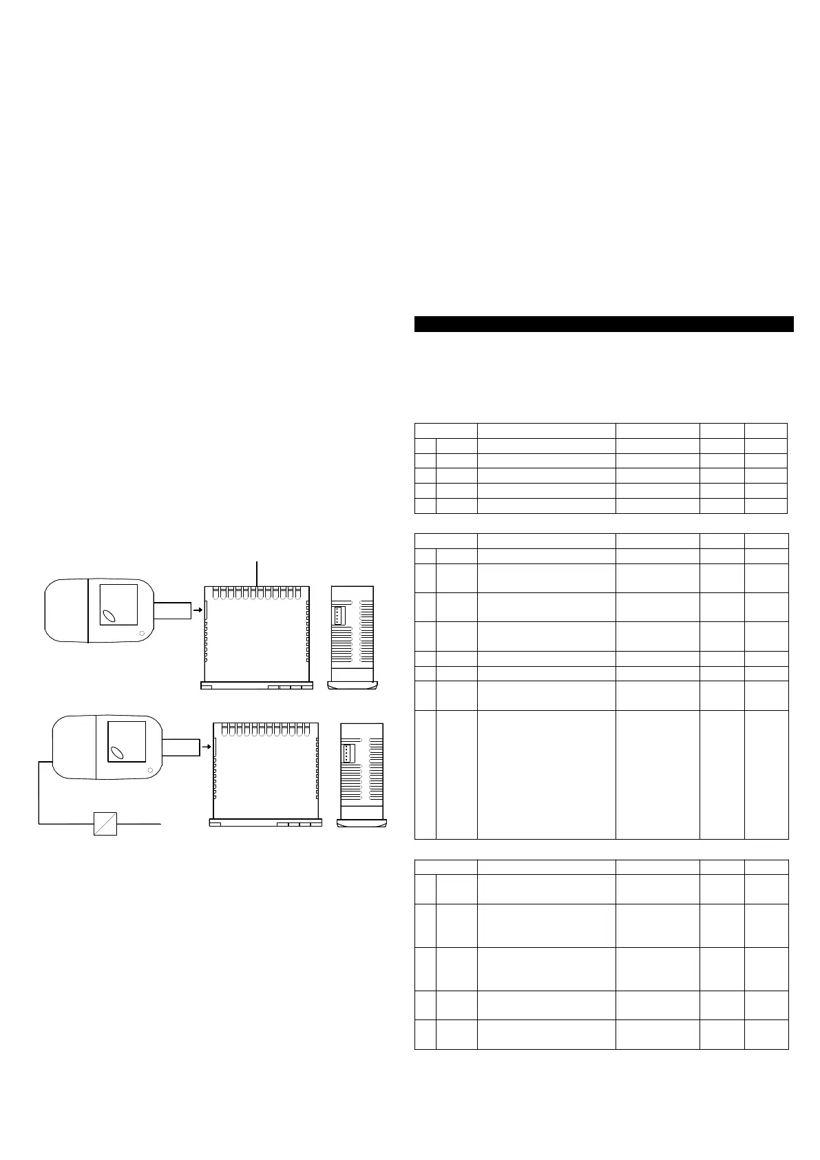
4.13 - PARAMETERS CONFIGURATION BY “A01”
The instrument is equipped with a connector that allows the
transfer from and toward the instrument of the functioning
parameters through the device A01 with 5 poles connector.
This device it’s mainly useable for the serial programming of the
instruments which need to have the same parameters configuration
or to keep a copy of the programming of an instrument and allow its
rapid retransmission.
To use the device A01 it’s necessary that the device or instrument
are being supplied.
Instrument supplied and device not supplied
To transfer the configuration of an instrument into the device
(UPLOAD) it is necessary to proceed in the following way:
1) position both dip switch of A01 in the OFF mode.
2) connect the device to the instrument TLY plugging the special
connector.
3) verify that the instrument or the device are supplied
4) observe the indication led on the device A01: if it results green
this means that a configuration is already loaded on the device
while if it results green blinking or red blinking this means that it has
not been loaded any valid configuration on the device .
5) press the button placed on the device.
6) observe the indication led : after having pressed the button, the
led becomes red and therefore, at the end of the data transfer, it
becomes green.
7) now it is possible to disconnect the device.
To transfer the configuration loaded on the device onto an
instrument of the same family (DOWNLOAD), it is necessary to
proceed in the following way:
1) position both dip switch of A01 in the ON mode.
2) connect the device to an instrument TLY having the same
features of the one from which has been downloaded the desired
configuration, plugging the special connector.
3) verify that the instrument or the device are supplied.
4) observe the indication led on the device A01: it has to result
green, because if the led results green blinking or red blinking, this
means that on the device it has not been downloaded any valid
configuration and therefore it’s useless to continue.
5) if the les results green, press the button placed on the device.
6) observe the indication led : after having pressed the button, the
led becomes red and therefore, at the end of the data transfer, it
becomes green.
7) now it is possible to disconnect the device.
For additional info, please have a look at the A01 instruction
manual.
5 - PROGRAMMABLE PARAMETERS TABLE
Here below is a description of all the parameters available on the
instrument. Some of them may not be present, either due to the
fact they depend on the type of instrument or because they are
automatically disabled as unnecessary.
Group
]
SP (parameters relative to Set Point)
Par. Description Range Def. Note
1 SPAt Active Set point 1 ÷ 2 1
2 SP1 Set Point 1 SPLL ÷ SPHL 0.0
3 SP2 Set Point 2 SPLL ÷ SPHL 0.0
4 SPLL Minimum Set Point -58 ÷ SPHL -50.0
5 SPHL Maximum Set Point SPLL ÷ 302 100.0
Group
]
InP (parameters relative to measuring inputs)
Par. Description Range Def. Note
6 SEnS Probes Type Ptc - ntc Ptc
7 OFS1 Pr1 Probe (cell)
Calibration
-30 ÷ 30
°C/°F
0.0
8 OFS2 Pr2 Probe (evaporator)
Calibration
-30 ÷ 30
°C/°F
0.0
9 Pr 2 Pr2 Probe Presence
(evaporator)
On - OFF On
10 Unit Unit of measurement °C - °F °C
11 dP Decimal point On - OFF On
12 FiL Measurement filter OFF ÷ 20.0
sec
2.0
13 diSP Variable visualized
normally on display:
OFF=Display off
Pr1= measurement
probe Pr1
Pr2= measurement
probe Pr2
SP= Active Set Point
CL= Clock time
OFF - Pr1 -
Pr2 - SP - CL
Pr1
Group
]
rEG (parameters relative to temperature control)
Par. Description Range Def. Note
14 HSEt Differential 0 ÷ 30
°C/°F
2.0
15 tonE Activation time output
OUT for probe Pr1
broken
OFF ÷ 99.59
min.sec
OFF
16 toFE Deactivation time
output OUT for probe
Pr1 broken
OFF ÷ 99.59
min.sec
OFF
17 Func Function mode output
OUT
HEAt - CooL CooL
18 tCC Continuous cycle Time OFF ÷ 99.59
hrs.min
OFF
Ascon Tecnologic - TLY25 - OPERATING INSTRUCTIONS - PAG. 8