dEF= defrosting
FAn= fans
AuS= Auxiliary
ALt= Silenceable alarm
AL= Alarm not
silenceable
ALL= memorised alarm
61 Out2 Configuration of output
function OUT2:
see “Out1”
OFF/Out/dEF/
FAn/AuS/ALt/
AL/ALL/ -ALt/
-AL/ -ALL
dEF
62 Out3 Configuration of output
function OUT3:
see “Out1”
OFF/Out/dEF/
FAn/AuS/ALt/
AL/ALL/ -ALt/
-AL/ -ALL
FAn
63 Out4 Configuration of output
function OUT4:
see “Out1”
OFF/Out/dEF/
FAn/AuS/ALt/
AL/ALL/ -ALt/
-AL/ -ALL
ALt
Group
]
PAn (parameters relative to configuration of the keyboard)
Par. Description Range Def. Note
64 Fbd Function mode key
DOWN/AUX:
OFF= No function
1= Auxiliary output
command
2= Continuous cycle
command
3= Selection of active
Set Point
4= Switch on/Switch off
(Stand-by)
OFF / 1 / 2 / 3
/ 4
OFF
65 USrb Function mode key U:
see “Fbd”
OFF / 1 / 2 / 3
/ 4
OFF
66 PASS Access Password to
parameter functions
OFF ÷ 9999 OFF
Group
]
CLO (parameters relative to the internal clock)
Par. Description Range Def. Note
67 StCL Current time 0.00 ÷ 23.59
hrs.min
0.00
68 CLOF Daily calibration of
clock
-20 ÷ 20
sec
0
6 - PROBLEMS, MAINTENANCE AND WARRANTY
6.1 - SIGNALLING
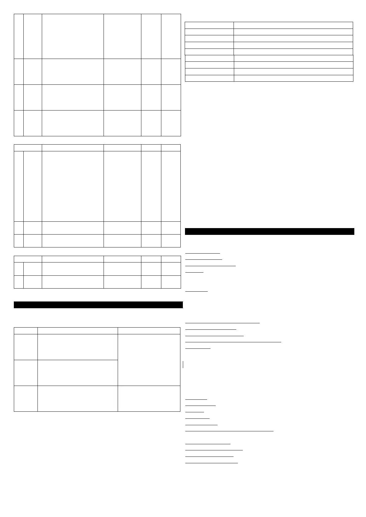
Error Signalling:
Error Reason Action
E1
-E1
The probe Pr1 may be
interrupted or in short circuit,
or may measure a value
outside the range allowed
Check the correct
connection of the
probe with the
instrument and check
the probe works
correctly
E2
-E2
The probe Pr2 may be
interrupted or in short circuit,
or may measure a value
outside the range allowed
EEPr Internal memory error Check and if
necessary re-
programme the
parameters function.
In Cell probe error status, the output OUT behaves as set by the
parameters “tonE” and “toFE”.
HI Maximum temperature alarm in progress
LO Minimum temperature alarm in progress
AL Digital input alarm in progress
AP Door open
6.2 - CLEANING
We recommend cleaning of the instrument with a slightly wet cloth
using water and not abrasive cleaners or solvents which may
damage the instrument.
6.3 - WARRANTY AND REPAIRS
The instrument is under warranty against manufacturing flaws or
faulty material, that are found within 18 months from delivery date.
The warranty is limited to repairs or to the replacement of the
instrument.
The eventual opening of the housing, the violation of the instrument
or the improper use and installation of the product will bring about
the immediate withdrawal of the warranty’s effects.
In the event of a faulty instrument, either within the period of
warranty, or further to its expiry, please contact our sales
department to obtain authorisation for sending the instrument to our
company.
The faulty product must be shipped to Ascon Tecnologic with a
detailed description of the faults found, without any fees or charge
for Ascon Tecnologic, except in the event of alternative
agreements.
7 - TECHNICAL DATA
7.1 - ELECTRICAL DATA
Power supply: 12 VAC/VDC, 100..240 VAC +/- 10%
Frequency AC: 50/60 Hz
Power consumption: 3 VA approx.
Input/s: 2 inputs for temperature probes: PTC (KTY 81-121,
990 @ 25 °C) or NTC (103AT-2, 10K @ 25 °C); 1 digital
input for free voltage contacts
Output/s: 4 relay outputs SPST-NO. 16 A Max. for common (pin. 1).
supply H type : OUT1 (16A-AC1, 6A-AC3 250 VAC), OUT 2,3,4
(5A-AC1, 2A-AC3 250 VAC).
supply F type: OUT1 (16A-AC1, 6A-AC3 250 VAC), OUT 2,3,4 (8A-
AC1, 3A-AC3 250 VAC)
Electrical life for relay outputs: 100000 operat. (VDE om.)
Installation category: II
Measurement category: I
Protection class against electric shock: Class II for Front panel
Insulation: Reinforced insulation between the low voltage part
(supply H type and relay outputs) and front panel; Reinforced
insulation between the low voltage section (supply type H and relay
outputs) and the extra low voltage section (inputs); Reinforced
between supply and relay outputs; No insulation between supply F
type and inputs.
7.2 - MECHANICAL DATA
Housing: Self-extinguishing plastic, UL 94 V0
Dimensions: 33 x 75 mm, depth 64 mm
Weight: 115 g approx.
Mounting: Flush in panel in 29 x 71 mm hole
Connections: 2,5 mm
2
screw terminals block
Degree of front panel protection : IP 65 mounted in panel with
gasket
Pollution situation: 2
Operating temperature: 0 ... 50 °C
Operating humidity: 30 ... 95 RH% without condensation
Storage temperature: -10 ... +60 °C
Ascon Tecnologic - TLY25 - OPERATING INSTRUCTIONS - PAG. 10
Other Signalling:
Message Reason
od Delay in switching on in progress
dEF Defrosting in progress with “dLo”=Lb
PdEF Post-defrosting in progress with “dLo”=Lb
CC Continuous cycle in progress

 Loading...


