Note that during defrosting, the temperature alarms are disabled
during the whole cycle and also afterwards for the time set in the
parameter “dALd” (see par. 4.9).
4.7 - MANUAL DEFROST
To start up a manual defrosting cycle, press the key UP/DEFROST
when it is not in programming mode and keep it pressed for about 5
seconds after which, if the conditions are correct, the led DEF will
light up and the instrument will carry out a defrosting cycle.
The start-up or switch off commands of a defrosting cycle can also
be given by the digital input that are correctly programmed (see
par. 4.10).
4.8 - EVAPORATOR FANS CONTROL
All the parameters concerning fan control are contained in the
group “
]
FAn”.
The control of the fans on the output configured as “FAn”
depending on determined control statuses of the instrument and
the temperature measured by the probe Pr2.
In the case that the probe Pr2 is not used (parameter “Pr 2” = OFF)
or in error (E2 o -E2) , the output FAN is activated only depending
on the parameters “FCOF” and “FEdF”.
The parameter “FCOF” decides whether the fans must always be
switched on independently of the compressor status (“FCOF”=On)
or be switched off together with the compressor (“FCOF”=OFF).
The parameter “FEdF” instead decides whether the fans must
always be switched on independently of the defrosting status
(“FEdF”=On) or switched off during defrosting (“FEdF”=OFF).
In this latter case, it is possible to delay the start up of the fans
even after the end of the defrosting of the time set in the parameter
“Fd”.
When the probe Pr2 is used (par. “Pr 2” = on) the fans, as well as
being conditioned by the parameters “FCOF” and “FEdF”, are also
conditioned by the temperature control.
It is possible to set the disablement of the fans when the
temperature measured by the probe Pr2 is higher than the one set
in the parameter “FLt” (temperature too hot) or when it is lower
than the one set in the parameter “Fct” (temperature too cold).
The relative differential that can be set in parameter “dF” is also
associated with these parameters.
d F
d F
tim e
F A n
o ff
O N
F c t
P r2
T e m p .
F L t
o ff o ff
O N
4.9 - ALARM FUNCTIONS
All the parameters concerning the alarm functions are contained in
group “
]
AL”.
The alarm functions of the instrument work on the output desired, if
configured by the parameters “O1F”, “O2F”, “O3F”, “OF4”
depending on what is set on the said parameters.
The possible selections of these parameters for the alarm signalling
function are:
= ALt - when one wants the output to be activated in alarm and
can be disabled (alarm silencing) manually by pressing any key of
the instrument (typical application for sound signal).
= AL - when one wants the output to be activated in alarm status
but cannot be disabled manually and are therefore only disabled
when the alarm status ceases (typical application for a light signal).
= ALL - when one wants the output to be activated in alarm status
and that they remain activated even when the alarm has ceased
(see par.4.9.4) Disablement (recognition of memorised alarm) can
only be carried out manually by pressing any key when the alarm
has ended (typical application for light signal).
= -ALt - when one wants the function described as ALt but with an
inverse function (output activated in normal condition and disabled
in alarm status).
= -AL - when one wants the function described as AL but with
inverse logic (output activated in normal conditions and disabled in
alarm status).
= -ALL - when one wants the function described as ALL but with
inverse working logic (output activated in normal conditions and
disabled in alarm status).
When no alarms are present, the green LED OK is lit.
Any active alarm is shown on the instrument display with the
lighting up of the AL led and the switching off of the led OK.
Any silenced or memorised alarm status is shown by the AL led
flashing .
The alarm conditions of the instrument are:
- Probe errors “E1”, “-E1”, “E2, “-E2”
- temperature alarms “HI” and “LO”
- External alarms “AL”
- Open door alarm “AP”
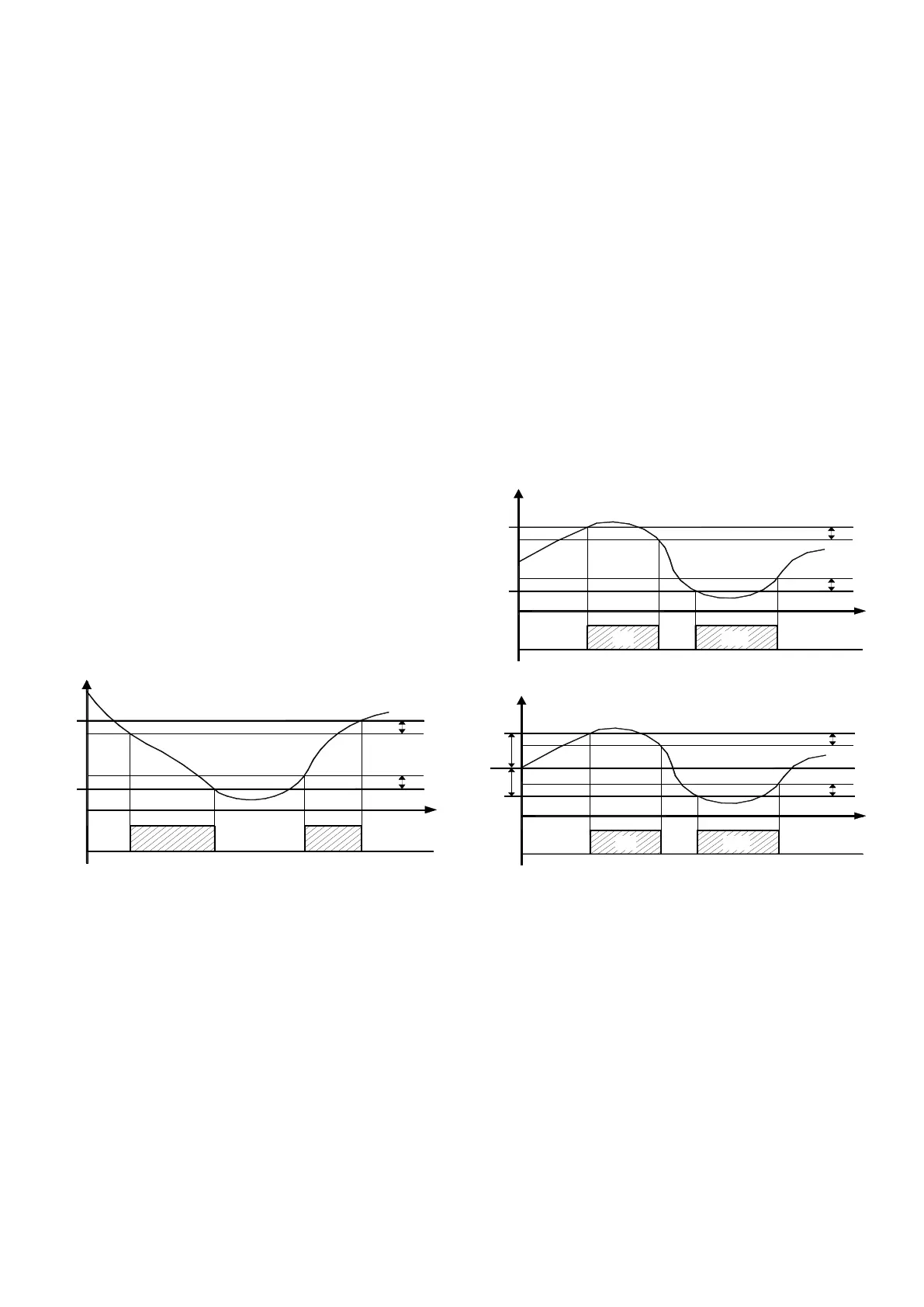
4.9.1 - TEMPERATURE ALARMS
The temperature alarms work according to the probe Pr1
measurements, the type of alarm set in the parameter “Aty” the
alarm thresholds set in parameters “HAL” (maximum alarm) and
“LAL” (minimum alarm) and the relative differential “dAL”.
Through the parameter “Aty” it is possible to set the alarm
thresholds “HAL” and “LAL” which must be considered as absolute
(“Aty”=Ab)
d A L
d A L
tim e
A L
o ff
O N
L A L
H I
H A L
T e m p .
P r1
L O
o ff o ff
O N
or relative to the active Set Point (“Aty”=dE).
tim e
d A L
d A L
A L
o f f
O N
H I
L A L
S P
H A L
T e m p .
P r1
L O
o ff o ff
O N
Using some parameters it is also possible to delay the
enablement and the intervention of these alarms.
These parameters are:
“PAL” - is the temperature alarm exclusion time on switching on
the instrument if the instrument is in alarm status when it is
switched on.
“dALd” - is the temperature alarm exclusion time at the end of
defrosting (and , if programmed, at the end of draining)
"dALc" - is the temperature alarm exclusion time at the end of a
continuous cycle.
“ALd” - is the temperature alarm delay activation time
The temperature alarm is enabled at the end of exclusion time and
is enabled after the “ALd” time when the temperature measured by
the probe Pr1 exceeds or goes below the respective maximum and
minimum alarm thresholds.
The alarm thresholds will be the same as those set on the
parameters “HAL” and LAL” if the alarms are absolute (“Aty”=Ab)
Or will be the values [”SP”+”HAL”] and [”SP”-”LAL”] if the alarms
are relative (“Aty”=dE).
The maximum and minimum temperature alarms can be disabled
by setting the relative parameters "HAL" and "LAL" = OFF.
Ascon Tecnologic - TLY25 - OPERATING INSTRUCTIONS - PAG. 6

 Loading...


