12
3 - Electrical Connections
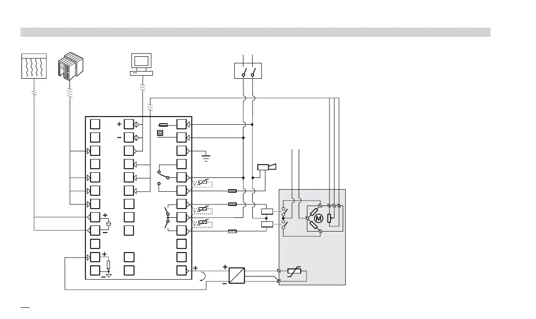
3.3 EXAMPLE OF WIRING DIAGRAM (VALVE CONTROL)
B
Notes:
1] Make sure that the power supply voltage is
the same indicated on the instrument.
2] Switch on the power supply only after that
all the electrical connections have been
completed.
3] In accordance with the safety regulations,
the power supply switch shall bring the
identification of the relevant instrument. The
power supply switch shall be easily acces-
sible from the operator.
4] The instrument is PTC protected. In case
of failure it is suggested to return the instru-
ment to the manufacturer for repair.
5] To protect the instrument internal circuits
use:
- 2 AT fuse for Relay outputs (220 Vac)
- 4 AT fuse for Relay outputs (110 Vac)
- 1 AT fuse for Triac outputs
6] Relay contacts are already protected with
varistors.
Only in case of 24 Vac inductive loads,
use model A51-065-30D7 varistors (on
request)
SupervisoryCommands
RS485
Power
supply
switch
Alarm
V
~
[3]
C
IL1
IL2
IL3
[6]
[6]
[5]
[5]
[5]
OP3
OP1
OP2
°C
C
Retransm.
I
Pt100
[6]
Transmitter
4…20mA
24V
V ~
Servomotor
Rj
PTC
12
11
10
9
8
7
6
5
4
3
2
1
24
23
20
19
36
35
34
33
32
31
30
29
28
27
26
25
18
17
16
15
14
13
21
x5-uk-ed5 17-09-2009 14:53 Pagina 12
 Loading...


