6
5
4
3
2
1
28
27
30
29
26
25
7
19
31
8
20
32
9
33
10
34
11
23
35
12
24
36
16
15
18
17
14
13
21
6
5
4
3
2
1
28
27
30
29
26
25
7
19
31
8
20
32
9
33
10
34
11
23
35
12
24
36
16
15
18
17
14
13
21
A B
E C D CD
A B
E C D CD
11
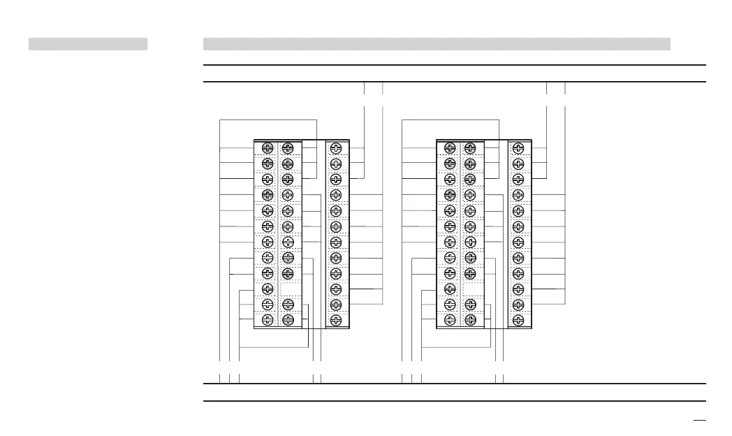
3 - Electrical Connections
PRECAUTIONS
B
Despite the fact that the instru-
ment has been designed to work
in an harsh and noisy environ-
mental (level IV of the industrial
standard IEC 801-4), it is recom-
mended to follow the following
suggestions.
A
All the wiring must comply with
the local regulations.
The supply wiring should be rout-
ed away from the power cables.
Avoid to use electromagnetic
contactors, power Relays and
high power motors nearby.
Avoid power units nearby, espe-
cially if controlled in phase angle
Keep the low level sensor input
wires away from the power lines
and the output cables.
If this is not achievable, use
shielded cables on the sensor
input, with the shield connected
to earth.
Conduit for supply and output cables
Conduit for low level sensor cables
3.2 SUGGESTED WIRES ROUTING
B
A = Supply
B = Outputs
C = Analog inputs
D = Analogue output
E = Digital input
Serial Comm.s
x5-uk-ed5 17-09-2009 14:53 Pagina 11
 Loading...


