60
7 - Programmed Setpoint
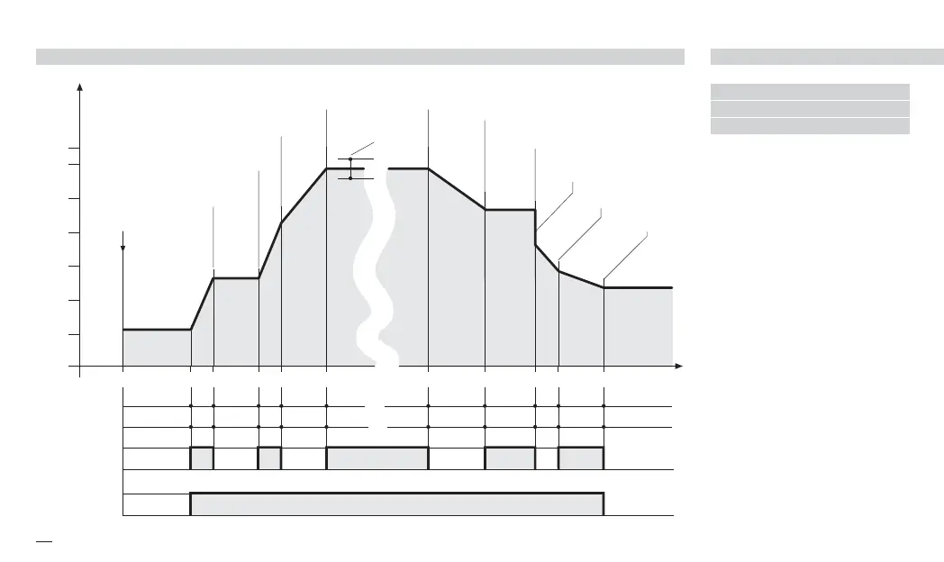
EXAMPLE OF SETPOINT PROFILE 7.2 SETPOINT PROGRAMMER O
300
250
200
150
100
50
350
1° 2° 3° 4° 5° 9° 10° 11°/12° 13° 14° End
300 50 70 80 110 170 190 210 230 250
t1 t2 t3 t4 t5 t9 t10 t11/t12 t13 t14
Segment Initial
Time
t0
Program
start
°C Setpoint
#sp. I
#sp. 2
#sp. 3
#sp. 9
#sp.10
#sp.11
#sp.13
#sp.12
Maximum
allowed deviation
#CIo
#Opn
OP3 digital
output
band
#sp.14
#sp. f
#sp. 0
#sp. 4
#CIo
#Opn
OP4 digital
output
time
7.2.1 MAXIMUM
ALLOWED
DEVIATION (
bbaanndd
)
If the PV controlled input value
exceeds the band, centred
around the SP, the segment time
is extended of the same time the
PV input stays out of the band.
The band width is defined in a
parameter of the program seg-
ment.
The actual segment period is
calculated as
ti..== +Ti
x5-uk-ed5 17-09-2009 14:53 Pagina 60
 Loading...


