Conf
L.inp
IL1
IL2
éOFF
éOFF
IL3
éOFF
30
4 - Operation
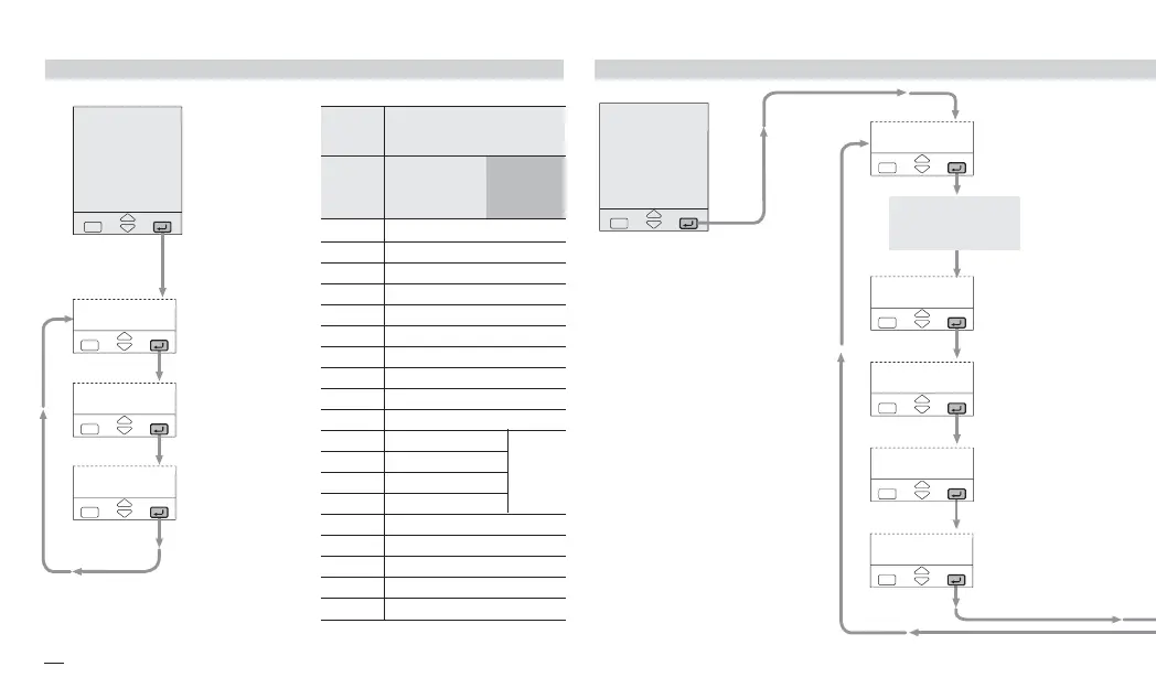
4.3.4 DIGITAL INPUTS CONFIGURATION 4.3.5 ALARM S CONFIGURATION
IL1 digital input
function
see table 10
IL2 digital input
function
see table 10
IL3 digital input
function
see table 10
Conf
ALM
bloc
éno
Ltch
éno
A1.Ou
éOP1
AL. 1
éOFF
donb
éno
AL1 alarm type
see table 11
AL1 addressing
OP1 / OP2 [1]
OP3 / OP4 [2]
AL1 latching
no / yeS
AL1 start-up
disabling
no / yeS
Disables AL1 if a
sensor break occurs
no / yeS
NOT AVAILABLE
OF
AL. 1 = OFF
[1] OP1 and OP2 outputs can be
used as alarm outputs if they
are not used as control out-
puts.
[2] OP3 and OP4 can be related
to the program (if option
installed).
slo.1
s.p. slope disable
H.pU
Measure hold
r.=H.
Program Run/Stop
Description
Tab. 10
Digital Inputs
Functions
éIl1
éIl2
éIl3
Value
Off
Not used
l=r
Local/Remote
A.Man
Auto/Man
s.p. 1
1
st
stored Setpoint
s.p. 2
2
nd
stored Setpoint
keb.I
Keyboard lock
F.Out
Output forcing mode
Prg.1
1
st
program
Prg.2
2
nd
program
Prg.3
3
rd
program
s.p. 3
3
rd
stored Setpoint
Prg.4
4
th
program
rSt
Program reset
up to
3
BLck
Reset blocking
neHt
Next segment
ack
Alarm acknowledge
x5-uk-ed5 17-09-2009 14:53 Pagina 30
 Loading...


