ASCON TECNOLOGIC - TLZ 12 P - OPERATING INSTRUCTIONS - Vr.02 - ISTR-MTLZ12PENG02- PAG. 5
= 3 - External alarm signal with contact normally open: on closing
the input the alarm is activated and the instrument visualises AL
and the measured temperature alternately on the display.
= -1 - defrosting commencement command with contact normally
closed : similar to “diF”=1 but with function logic reversed.
= -2 - defrosting end command with contact normally closed :
similar to “diF”=2 but with function logic reversed.
= -3 - External alarm signal with contact normally closed : similar to
“diF”=3 but with function logic reversed.
4.8 - FUNCTIONING OF KEY “U”
The U key function can be defined by the parameter “USrb” and
can be configured for the following functions:
= OFF - The key U carries out no function.
= 1 - Pressing the key for at least 1 second, it is possible to switch
the instrument from the ON status to Stand-by status and vice
versa.
4.9 - PARAMETERS CONFIGURATION BY “A01”
The instrument is equipped with a connector that allows the transfer
from and toward the instrument of the functioning parameters
through the device A01 with 5 poles connector.
This device it’s mainly useable for the serial programming of the
instruments which need to have the same parameters configuration
or to keep a copy of the programming of an instrument and allow its
rapid retransmission.
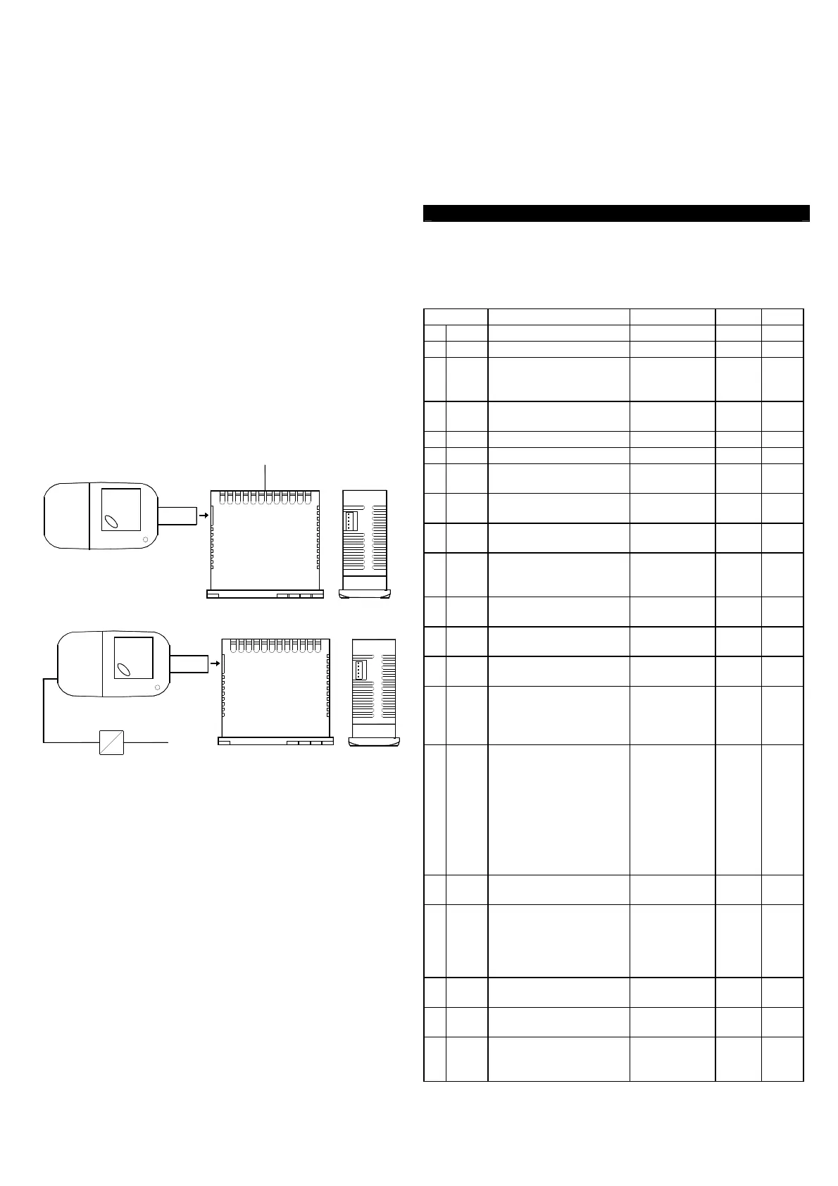
To use the device A01 it’s necessary that the device or instrument
are being supplied.
Instrument supplied and device not supplied
SUPPLY
Instrument supplied from the device
SUPPLY ADAPTER
12 VDC AC SUPPLY
To transfer the configuration of an instrument into the device
(UPLOAD) it is necessary to proceed in the following way:
1) position both dip switch of A01 in the OFF mode.
2) connect the device to the instrument TLZ plugging the special
connector.
3) verify that the instrument or the device are supplied
4) observe the indication led on the device A01: if it results green
this means that a configuration is already loaded on the device
while if it results green blinking or red blinking this means that it has
not been loaded any valid configuration on the device .
5) press the button placed on the device.
6) observe the indication led : after having pressed the button, the
led becomes red and therefore, at the end of the data transfer, it
becomes green.
7) now it is possible to disconnect the device.
To transfer the configuration loaded on the device onto an
instrument of the same family (DOWNLOAD), it is necessary to
proceed in the following way:
1) position both dip switch of A01 in the ON mode.
2) connect the device to an instrument TLz having the same
features of the one from which has been downloaded the desired
configuration, plugging the special connector.
3) verify that the instrument or the device are supplied
4) observe the indication led on the device A01: it has to result
green, because if the led results green blinking or red blinking, this
means that on the device it has not been downloaded any valid
configuration and therefore it’s useless to continue.
5) if the les results green, press the button placed on the device.
6) observe the indication led : after having pressed the button, the
led becomes red and therefore, at the end of the data transfer, it
becomes green.
7) now it is possible to disconnect the device.
For additional info, please have a look at the A01 instruction
manual.
5 - PROGRAMMABLE PARAMETERS TABLE
Here below is a description of all the parameters available on the
instrument. Some of them may not be present, either due to the
fact they depend on the type of instrument or because they are
automatically disabled as unnecessary.
Par. Description Range Def. Note
1
SPLL
Minimum Set Point -99.9 ÷ SPHL
-99.0
2
SPHL
Maximum Set Point SPLL ÷ 932.0
500.0
3
SEnS
Probe type
Pt10= Pt1000
Entc= NTC (PT-24C2)
Pt10 - Entc Pt10
4
OFS
Probe Calibration -30.0 ÷ 30.0
°C/°F
0.0
5
Unit
Unit of measurement °C - °F °C
6
dP
Decimal point On - OFF On
7
FiL
Measurement filter OFF ÷ 20.0
sec
2.0
8
HSEt
Differential 0.0 ÷ 30.0
°C/°F
2.0
9
tonE
OUT for probe broken
OFF ÷ 99.59
min.sec
OFF
10
toFE
broken
OFF ÷ 99.59
min.sec
OFF
11
Func
OUT
HEAt - CooL
CooL
12
dint
Defrosting interval OFF ÷ 24.00
hrs.min
6.00
13
dEFE
Lenght of defrost cycle 0.01 ÷ 99.59
min.sec
30.00
14
dCt
Defrosting intervals
Counting mode:
rt = real time
ct = On OUT time
rt - ct rt
15
dLo
Defrost display Lock:
OFF= display free
defrost
Lb= Lock on label “dEF”
“PdEF” (during post-
defrosting)
On - OFF - Lb
OFF
16
Etdu
unlock after defrost
0.0 ÷ 30.0
°C/°F
2.0
17
PSC
protection:
1= delay at switch on
2= delay after switch off
3= delay between starts
1 - 2 - 3 1
18
PtC
time
min.sec
OFF
19
od
Delay at power on OFF ÷ 99.59
min.sec
OFF
20
HAL
threshold
OFF ÷ 100.0
°C/°F
OFF

 Loading...


