Page 10 of 16
6.1 Description of components
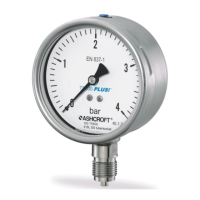
6.1.1 Scale with pointer
The pressure gauge is equipped with a dial and pointer according to EN 837-1, nominal size 100 mm or 160 mm.
6.1.2 Instrument connection
The instrument connection is located on the bottom (Model T5500-KF, T6500-KF) or eccentrically on the back (available
on Model T5500-KF only) of the instrument.
6.1.3 6.3.3 Vent valve
The vent valve (if present) is located on the top of the instrument. When the nipple (pull) is pulled out, the housing is
vented and the pressure built up in the housing due to temperature influence is relieved.
When the valve is closed, the degree of protection is IP66/IP67 according to EN 60529 / IEC 60529.
When the valve is open, the degree of protection is reduced to the minimum requirement according to EN ISO 80079-
37 chap. 5.2.2a
6.1.4 6.3.4 Blow out back cover/disc
The device has a blow-out disc (model T5500-KF) or a blow-out back cover (model T6500-KF) on the rear wall of the
housing. These serve as a safety device in accordance with EN 837-1 and enable automatic compensation of the internal
housing pressure, which can be caused by temperature influences in the housing, via a rubber diaphragm.
6.2 Accessories
Please contact the manufacturer for information on special sealing materials and accessories.
7 Transportation
The device must be protected against impact. Transport must be carried out exclusively in the glass-break-proof
packaging provided for transport. The device shall only be transported in a cleaned condition (free of residual media).
7.1 Delivery
The delivery is to be checked for completeness and transport damage. In case of transport damage, the delivery is not
to be accepted or only with reservation, the extent of damage is to be noted and, if necessary, a complaint is to be
initiated. In these cases, please contact our service department.
7.2 Storage
The storage of the devices should exclude external influences as far as possible to avoid damage to the devices.
Vibrations or impact effects must be avoided, and the limit values of the storage temperatures must be taken into
account.
Permissible storage temperature: -40 to +60°C
8 Assembly/Installation
8.1 Preparation
To ensure safe working during installation and maintenance, suitable shut-off valves must be installed in the system, by
means of which the unit can be
depressurized within the relevant plant for the purpose of repair or inspection,
subjected to a functional check on site.
During assembly/installation work, the system must be secured against being switched on again.

 Loading...