MPS-Series – Installation Guide
U-0664-0174.doc – Issue: 07 complete, approved
Page 15 of 24
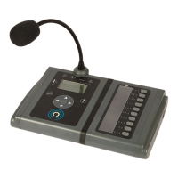
12. Offer up the microphone unit to the wall bracket and use two each of the supplied M5 hex screws and
washers to fasten the microphone to the wall bracket as shown in Figure 12 (page 15).
If used, fasten the microphone to the Right-Hand Side Bracket using one M5 hex screw and washer.
Figure 12 Fastening the microphone to the wall bracket
USE A 3 MM A/F HEX DRIVER
AND TO THE RIGHT-HAND
BRACKET, IF USED.
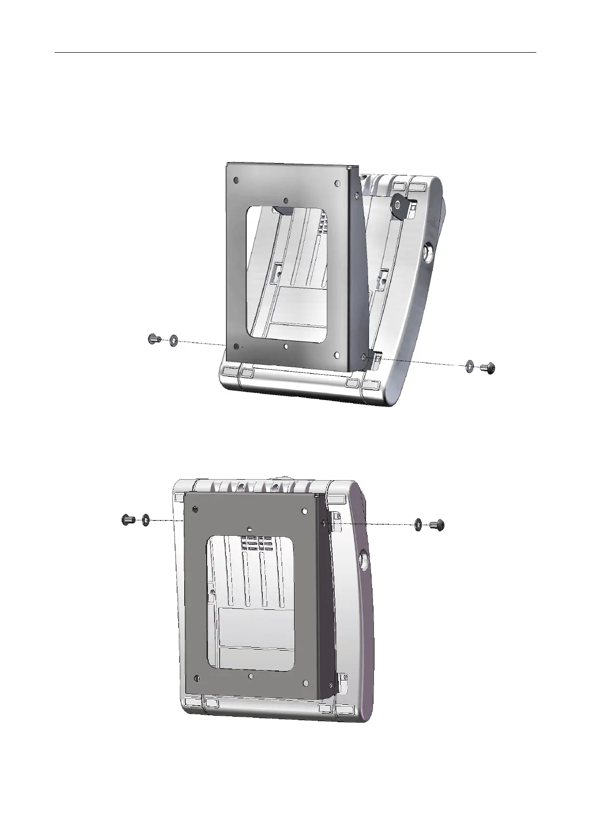
13. Use the two remaining M5 hex screws and washers to fully lock the microphone to the wall bracket;
see Figure 13 (page 15).
Figure 13 Locking the microphone to the wall bracket
USE A 3 MM A/F HEX DRIVER
OR THE RIGHT-HAND
BRACKET, IF USED.