33
English
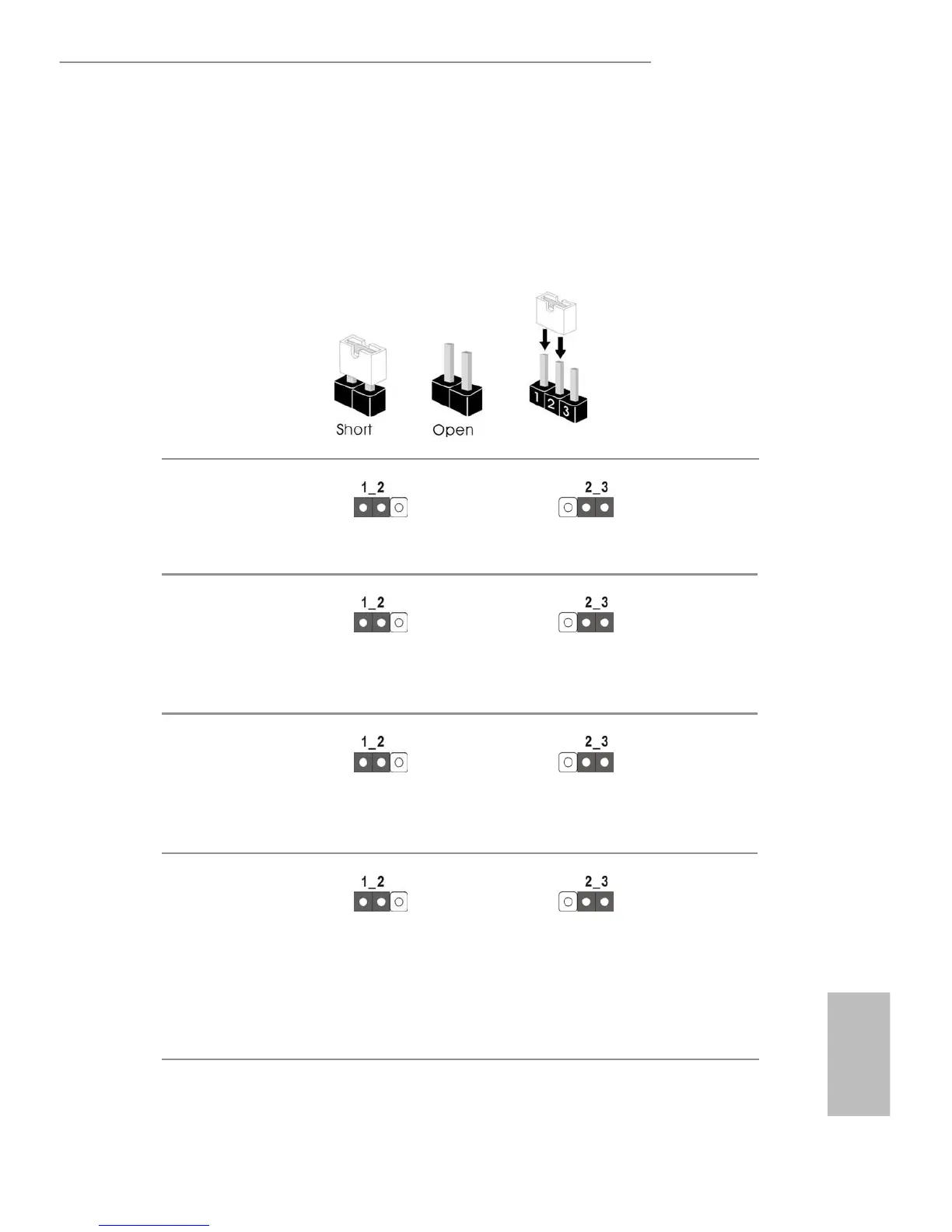
2.5 Jumper Setup
e illustration shows how jumpers are setup. When the jumper cap is placed on
the pins, the jumper is “Short”. If no jumper cap is placed on the pins, the jumper
is “Open”. e illustration shows a 3-pin jumper whose pin1 and pin2 are “Short”
when a jumper cap is placed on these 2 pins.
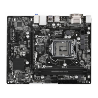
ME Recovery Jumper
(3-pin ME_RECOVERY1)
(See p.7, 10, 13 or 16)
Normal Mode (Default)
ME Recovery Mode
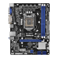
CPU PECI Mode Jumper
(3-pin PECI1)
(See p.7, 10, 13 or 16)
CPU PECI connected to PCH
CPU PECI connected to
BMC (Default)
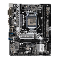
NCSI Mode Jumper
(3-pin NCSI_SEL1)
(See p.7, 10, 13 or 16)
NCSI is set to onboard LAN1
(Default)
NCSI is set to Mezzanine
Card
PMBUS Mode Jumper
(3-pin PMBUS_ALT_SEL)
(3-pin PMBUS_CLK_
SEL)
(3-pin PMBUS_SATA_
SEL)
(See p.7, 10, 13 or 16)
PMBus connected to BMC
(Default)
PMBus connected to PCH