English
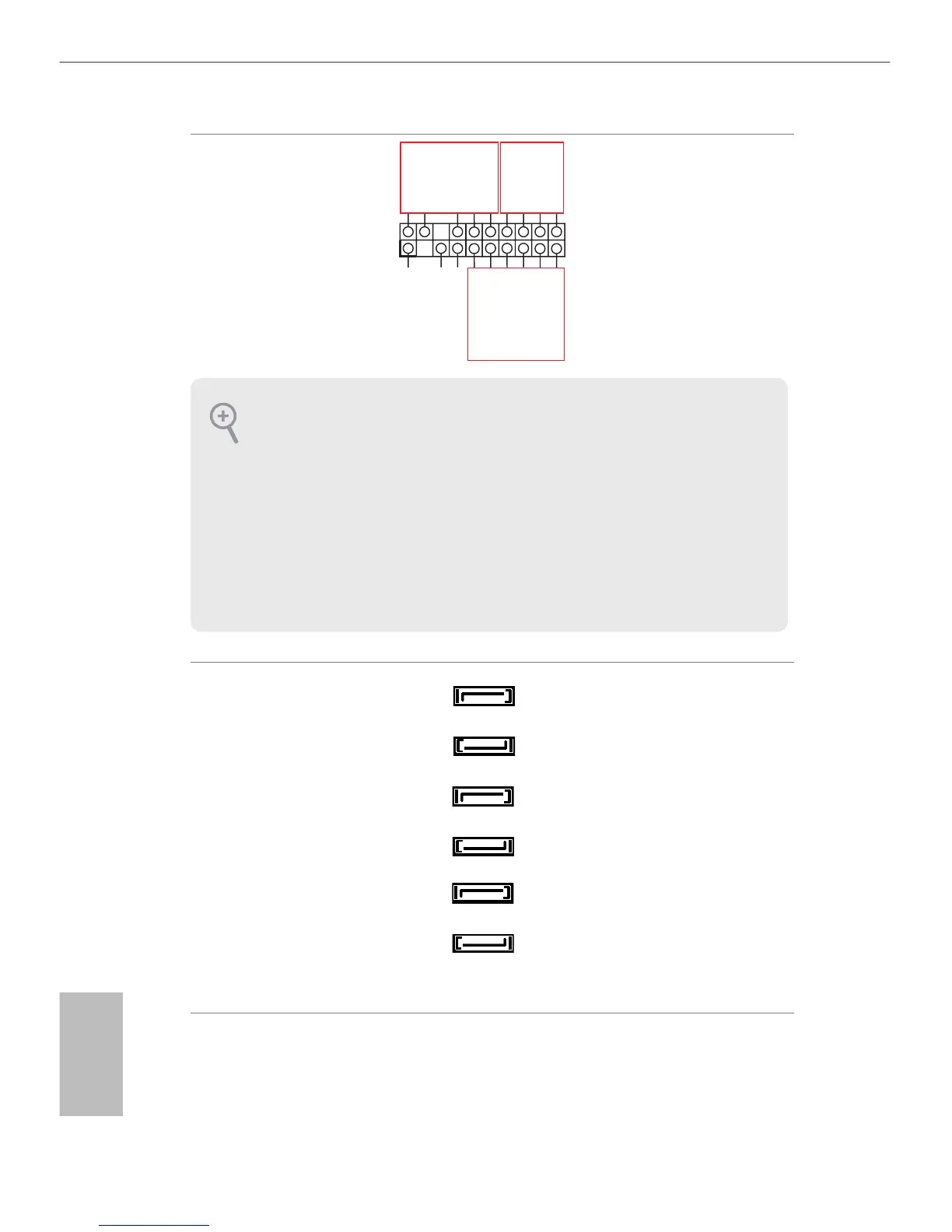
Auxiliary Panel Header
(18-pin AUX_ PANEL1)
(See p.7, 10, 13 or 16)
GND
12C_4_CLK#
NC
1
12C_4_DATA#
+5VSB
SFP+_1_LINK
LED_PWR
SFP+_2_LINK
LED_PWR
+5VSB
GND
GND
LOCATORLED1+
LOCATORLED1-
LOCATORBTN#
LOCATORLED2+
LOCATORLED2-
A
B
C
NC
is header supports multiple
functions on the front panel,
including front panel SMB,
internet status indicator.
Serial ATA3 Connectors
(SATA0)
(See p.7, 10, 13 or 16)
(SATA1)
(See p.7, 10, 13 or 16)
(SATA2)
(See p.7, 10, 13 or 16)
(SATA3)
(See p.7, 10, 13 or 16)
(SATA4)
(See p.7, 10, 13 or 16)
(SATA5)
(See p.7, 10, 13 or 16)
ese six Serial ATA3 (SATA3)
connectors support SATA
data cables for internal storage
devices. e current SATA3
interface allows up to 6.0 Gb/s
data transfer rate.
SATA0
SATA1
SATA2
SATA3
SATA4
SATA5
A. Front panel SMBus connecting pin (6-1 pin FPSMB)
is header allows you to connect SMBus (System Management Bus) equipment. It can
be used for communication between peripheral equipment in the system, which has slower
transmission rates, and power management equipment.
B. Internet status indicator (2-pin SFP+_1_LED, SFP+_2_LED)
ese two 2-pin headers allow you to use the Gigabit internet indicator cable to connect
to the LAN status indicator. When this indicator ickers, it means that the internet is prop-
erly connected.
C. Locator LED (6-pin LOCATOR)
is header is for the locator switch and LED on the front panel.