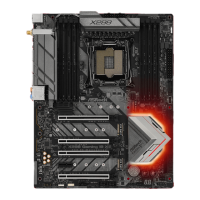
2.11.3 Installing Four CrossFireX
TM
-Ready Graphics Cards
Step 1
Insert one graphics card into PCIE1 slot,
another graphics card into PCIE2 slot, the
third graphics card into PCIE4 slot and the
last graphics card into PCIE5 slot. Make
sure that the cards are properly seated on
the slots.
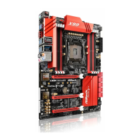
Step 2
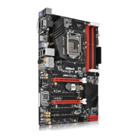
Use one CrossFire
TM
Bridge to connect
the graphics cards on PCIE1 and PCIE2
slots, another CrossFire
TM
Bridge to
connect the graphics cards on PCIE2 and
PCIE4 slots, and use the third CrossFire
TM
Bridge to connect the graphics cards on
PCIE4 and PCIE5 slots. (e CrossFire
TM
Bridge is provided with the graphics
card you purchase, not bundled with this
motherboard. Please refer to your graphics
card vendor for details.)
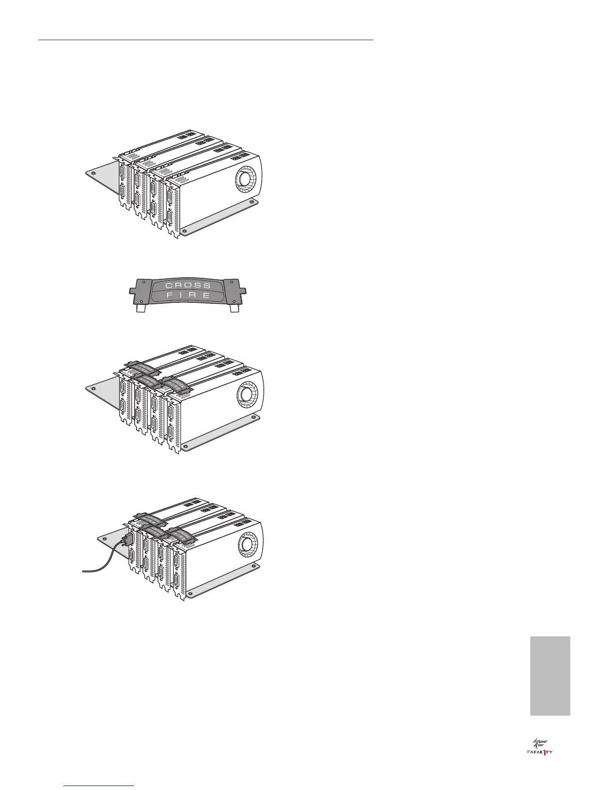
Step 3
Connect a VGA cable or a DVI cable to the
monitor connector or the DVI connec-
tor of the graphics card that is inserted to
PCIE1 slot.
CrossFire Bridge
 Loading...