13
R
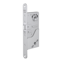
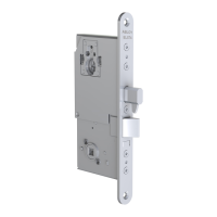
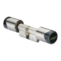
CABLING INSTRUCTIONS EL654, EL655 ENGLISH
DATA CABLE ABLOY EA216, 6 m, 9 x 0.14 mm2
BUS TERMINATION 120 Ω
In a bus network it is necessary to terminate the bus lines in order to avoid transmitting
refl ections. In this system, it is accomplished by one resistor. Please note that the lock case
itself does not include the bus termination, but if the lock case is installed with EA470 control
unit, the bus termination can be set by DIP-switch in the control unit.
Note! If more than one termination in the network is switched ON, this may cause problems.
Only one 120 Ω termination resistor is allowed.
SETTING THE GROUPS
It is possible to split the network devices into two logically independent groups. The lock is
set to group 1 when the loop connector is not connected.
When the loop connector is connected, the lock is set to group 2.
Note! When EL654/ EL655 is set alone (without auxiliary lock) in group 2, the blue wire in the
loop connector must be cut.
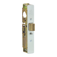
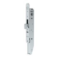
CONNECTION BETWEEN EL654/EL655 AND AUXILIARY LOCK CASE
It is possible to connect EL654/EL655 together with lock cases ABLOY EL480, EL482,
EL402 and EL490.
The wiring must be implemented by using ABLOY connection cables EA235 or EA236
depending on the lock type (see page 9).
The auxiliary lock case is activated by using the confi guration connector loop connector as
follows:
- Connect the loop connector to the EL654/EL655 cable (3-pin AMP connector).
- Turn the power off from EL654/EL655.
Note! The power must be turned off everytime you activate a new EL654/EL655 lock case.
Connect loop
connector
when installing
lock to group 2.
Grouping in a CAN network.
Group 2.
Group 1.
 Loading...