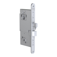
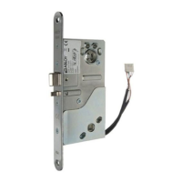
The 8800 Series Mortise Lock, now offered under the ASSA ABLOY ACCENTRA™ brand, is a robust locking solution designed for use with VN Escutcheon Trim and V Series Indicators. This comprehensive installation guide details the steps required for proper setup, ensuring secure and reliable operation.
Function Description:
The 8800 Series Mortise Lock is a high-security lock body designed for commercial and institutional applications. It integrates with various trim options and indicators to provide visual feedback on the lock's status (e.g., locked, unlocked, vacant, occupied). The lock mechanism includes a mortise lock body, levers, and a cylinder, offering secure access control. Depending on the specific function and options ordered, the lock can be configured with different indicator types, including cylinder, thumbturn, coin turn, or blank/no input. The rehanding capability of the indicator and the lock body ensures adaptability to various door configurations (LH, LHRB, RH, RHRB). The system is designed for ease of installation and maintenance, with clear instructions for preparing the door, installing the lock body, trim, cylinder, and front plate, and performing functional checks.
Important Technical Specifications:
- Compatibility: Designed for use with VN Escutcheon Trim and V Series Indicators.
- Door Handing: Adaptable for Left Hand (LH), Left Hand Reverse Bevel (LHRB), Right Hand (RH), and Right Hand Reverse Bevel (RHRB) doors.
- Indicator Types: Supports Cylinder (for inside or outside), Thumbturn (for inside), Coin Turn (for outside), and No Input/Blank (for inside or outside) indicators.
- Lock Screws: Uses #12 x 1-1/4" wood screws or #12-24 x 1-1/2" machine screws for temporary lock body installation.
- Through-bolt Screws: Uses two (2) #8-32 x 2-1/4" screws for securing inside escutcheon to outside escutcheon.
- Outside Front Screws: Uses two (2) flat head screws #8-32 x 1/4" for attaching the outside front.
- Standard Door Thickness: Specific parts (e.g., Indicator Spindle Cam - Cylinder/No Input / Blank, Indicator Spindle Cam - Cylinder Overtravel, Indicator Spindle Cam - Coin Turn) are designed for 1-3/4" standard thickness doors; contact the factory for other thicknesses.
- Part Numbers: A detailed list of part numbers is provided for various components, including indicator escutcheon (Consult Factory), indicator window (856F049), indicator display assemblies (e.g., 82-5602-4000 for Green Unlocked / Red Locked), and indicator spindle cams (e.g., 50-8800-9328 for Thumbturn).
- Tools Required: #2 & #3 Phillips Head Screwdrivers, Flat Blade Screwdriver, 1/8" Allen Wrench, 3/32" Drill Bit, and T-20 Torx Screw with Tamper Pin Driver.
- Door Preparation: Requires door preparation according to the 7088-0005 door marker template.
Usage Features:
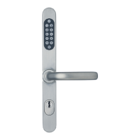
- Visual Status Indicators: The V Series Indicators provide clear visual feedback on the lock's status, enhancing security and convenience. This includes "Unlocked/Locked," "Vacant/Occupied," and icon-based indicators.
- Handing Flexibility: The lock and indicators can be rehanded to match various door configurations, ensuring broad applicability. Instructions are provided for verifying and adjusting the spindle cam position for both deadbolt and non-deadbolt functions.
- Multiple Input Options: Users can choose between cylinder, thumbturn, or coin turn mechanisms based on the desired level of access control and operational preference.
- Easy Installation Process: The manual provides a step-by-step guide, from door preparation to final functional checks, making the installation process straightforward for trained personnel.
- Secure Fastening: The use of specific screws and through-bolts ensures a secure and stable installation of the lock body and trim components.
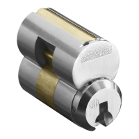
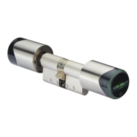
- Cylinder Integration: The design allows for easy threading and tightening of the cylinder, with clear instructions on proper key and cylinder rotation for correct operation. Interchangeable core cylinders are supported, though the core is not standard and must be requested separately.
- Lever Orientation: Instructions emphasize ensuring the outside lever assembly and plastic bushing are inserted with the lever horizontal, and aligning indicator spindles with the control hub for proper function.
Maintenance Features:
- Functional Check: A critical step in the installation process involves a thorough functional check to ensure all components operate correctly, including key rotation, latch retraction, deadbolt throw, lever operation, and indicator display accuracy. This helps identify and resolve issues early.
- Troubleshooting: The manual advises against forcing components if resistance is encountered during functional checks, directing users to re-check the indicator handing if necessary.
- Component Replacement: The detailed "Indicator Parts List" with part numbers facilitates easy identification and ordering of replacement parts for maintenance or repair. This includes individual components like indicator windows, display assemblies, and spindle cams.
- Clear Instructions for Adjustment: Specific instructions for adjusting the spindle cam position and tightening screws (e.g., cylinder clamp screw) allow for fine-tuning the lock's operation.
- Door Pocket Cleaning: The instruction to clean out the door pocket and door edge of debris prior to lock installation helps prevent operational issues caused by obstructions.
- Copyright and Support Information: The manual includes copyright information and contact details (1-855-557-5078 Ext. 2, www.accentra-assaabloy.com) for support, ensuring users can access assistance for maintenance or technical queries.