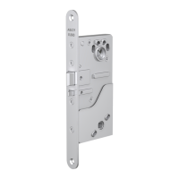
8800 Series Mortise Lock
Used with VN Escutcheon Trim and V Series Indicators
Installation Instructions
2
80-8800-0017-000 04/24
Copyright © 2023,2024, ASSA ABLOY ACCENTRA™ Access and Egress Hardware Group, Inc. All rights reserved. Reproduction in whole
or in part without the express written permission of ASSA ABLOY Access and Egress Hardware Group, Inc. is prohibited.
1-855-557-5078 Ext. 2 • www.accentra-assaabloy.com
Table of Contents
1. Tools Required ........................................................................................... 2
2. Indicator Variants ......................................................................................... 2
3. Lock Set Conguration ..................................................................................... 3
4. Rehanding Indicator (if required) ............................................................................ 3
5. Installation ............................................................................................... 4
1. Prepare Door for Mortise Lock ............................................................................ 4
2. Install Lock ............................................................................................ 4
3. Install Outside Trim ..................................................................................... 4
4. Install Inside Trim ....................................................................................... 5
5. Install Cylinder ......................................................................................... 5
6. Install Outside Front ..................................................................................... 5
7. Perform Functional Check ............................................................................... 6
6. Indicator Part List ......................................................................................... 7
1. Tools Required
#2 & #3 Phillips Head
Screwdrivers
Flat Blade
Screwdriver
1/8" Allen
Wrench
3/32" Drill Bit T-20 Torx Screw
with Tamper Pin
Driver
2. Indicator Variants
Depending on function and option
ordered, indicators are provided
in the following variations. These
instructions detail how to install with
cylinder, however other variations
follow similar instructions (Figure 1).
Contact factory for any questions.
Cylinder -
For Installation
on Inside or
Outside of Door
Figure 1
Thumbturn -
For Installation
on Inside
of Door
Coin Turn -
For Installation
on Outside
of Door
No Input/Blank -
For Installation
on Inside
or Outside
of Door
 Loading...