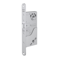
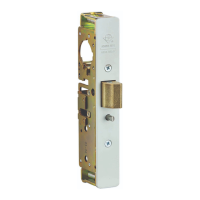
8800 Series Mortise Lock
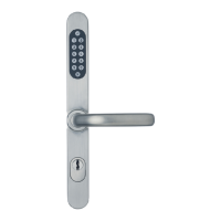
Used with VN Escutcheon Trim and V Series Indicators
Installation Instructions
6
80-8800-0017-000 04/24
Copyright © 2023,2024, ASSA ABLOY ACCENTRA™ Access and Egress Hardware Group, Inc. All rights reserved. Reproduction in whole
or in part without the express written permission of ASSA ABLOY Access and Egress Hardware Group, Inc. is prohibited.
1-855-557-5078 Ext. 2 • www.accentra-assaabloy.com
5. Installation, continued
5. Install Cylinder
1. Thread cylinder into lock until ush with escutcheon surface (Figure
9).
• Pull key slightly out of cylinder to help thread into lock body.
2. Tighten cylinder clamp screw with #2 Phillips screwdriver.
• Check operation and adjust if necessary.
NOTES:
• Key and cylinder must be positioned as Figure 10 shows.
• If double cylinder function is used, repeat steps 5.1 and 5.2 for
second cylinder.
• Interchangeable core cylinders require a control key to remove and
install the core. This is not provided standard. It must be requested
seperately.
7. Perform Functional Check
DO NOT FORCE if resistance is encountered during functional check.
Refer back to Rehanding Indicator (if required) section to ensure correct
handing. Rehand if necessary.
1. Insert key into cylinder (if present) and rotate:
• Ensure there is no friction against lock case or any other
obstructions.
2. Check key retracts latch:
• Key should rotate freely.
3. Throw deadbolt (if present):
• Check key retracts both deadbolt and latch.
4. Test levers:
• Conrm latch and deadbolt (if installed) retract.
5. Verify indicator displays correct status when locked and unlocked.
6. Install Outside Front
1. Tighten the two (2) lock screws completely (Figure 11).
2. Attach outside front with two (2) at head screws #8-32 x 1/4".
Figure 9
Figure 10
Figure 11
Cylinder
Clamp Screw
Cylinder
Key and cylinder must be rotated as shown.
Correct
Incorrect
Lock Screw
Outside Front
Lock Screw
#8-32
x 1/4"
Screws
 Loading...