Copyright © 2019-2020, ASSA ABLOY Accessories and Door Controls Group, Inc. All rights reserved. Reproduction in whole
or in part without the express written permission of ASSA ABLOY Accessories and Door Controls Group, Inc. is prohibited.
80-9360-1030-020 Rev 6 11/20
11
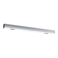
D6021/D6031 Double Unit Series (Push Side) Power Operator
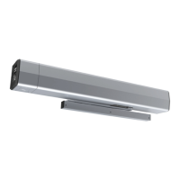
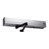
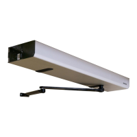
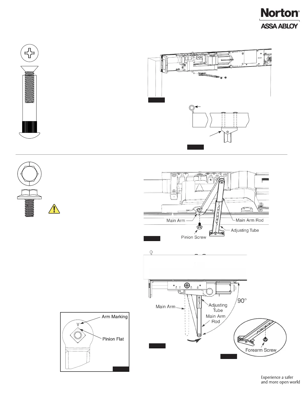
B. Install Main Arms.
A. Mount Adjusting Tubes and Shoes to doors.
Install Adjusting Tubes and Shoes and Main Arms
Figure 19
Figure 20
Figure 21
Figure 22
Figure 23
Figure 24
1. Using previously prepared holes in
doors, install two (2) 1/4-20 x 1-5/8"
screws through each shoe and into
sex bolts. (Figure 19)
NOTE: Orient shoe with short side
of shoe toward hinge. (Figure 20)
View from ceiling looking downward
Short Side
of Shoe
Hinge
1. Open door of your choosing.
2. Slide main arm rod into adjusting
tube. (Figure 21)
3. Place square of main arm onto closer
pinion. (Figure 21)
NOTE: Pinion at should be aligned
as shown. (Figure 22)
4. Attach main arm to pinion with
screw then tighten with 7/16"
wrench. (Figure 21)
5. With door closed, rotate main arm
away from hinge until adjusting tube
is perpendicular (90 degrees) with
door. (Figure 23)
6. While holding arm in position,
secure rod to adjusting tube with
forearm screw. (Figure 24)
7. Repeat on second door.
View from ceiling looking downward
 Loading...