Copyright © 2019, ASSA ABLOY Accessories and Door Controls Group, Inc. All rights reserved. Reproduction in whole or
in part without the express written permission of ASSA ABLOY Accessories and Door Controls Group, Inc. is prohibited.
80-9360-1030-020 Rev 6 11/20
8
D6021/D6031 Double Unit Series (Push Side) Power Operator
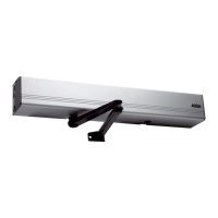
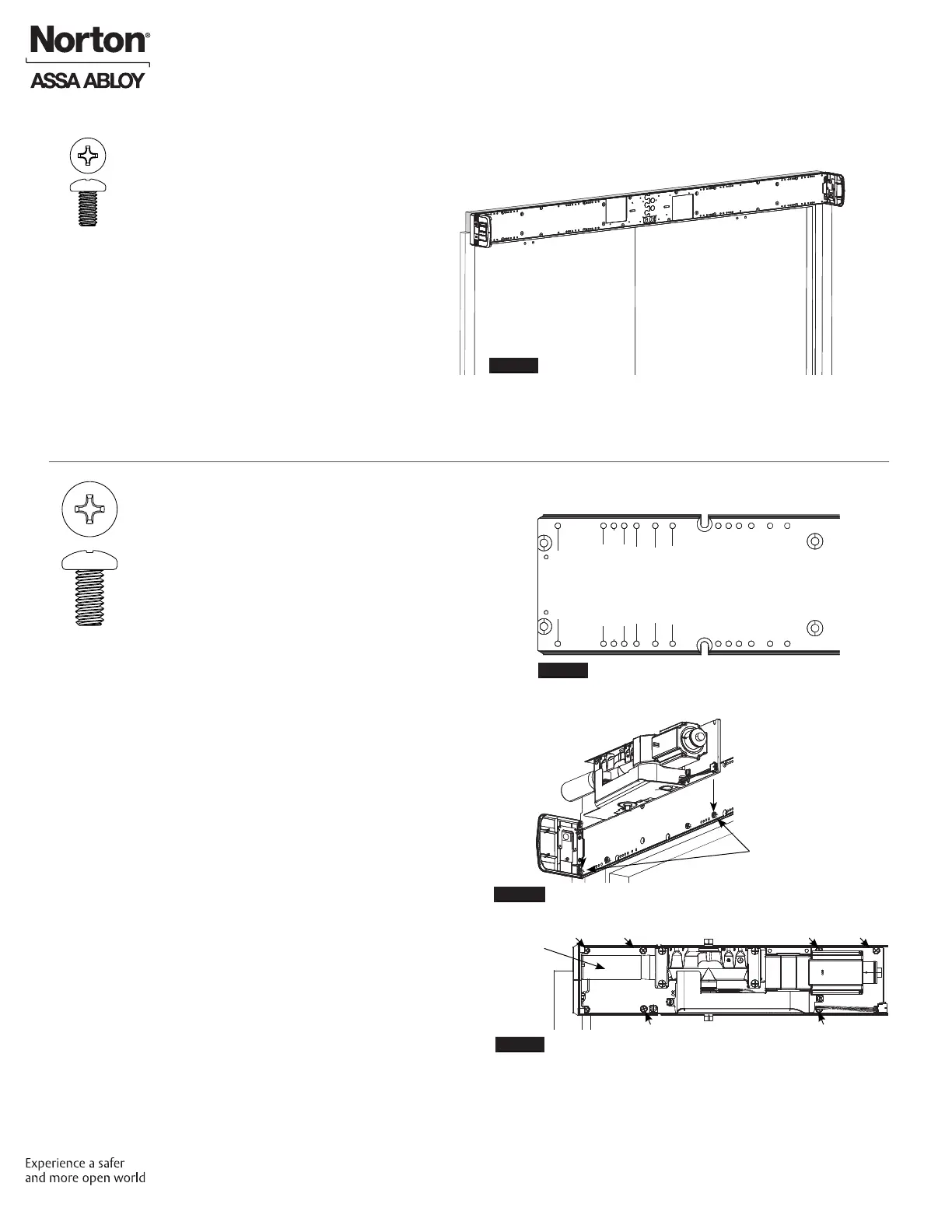
B. Install Operator LAP.
NOTE: Backplates are printed with text to assist
installation.
1. With backplates mounted to frame, use text to
locate holes along bottom of backplates that
correspond to your specic closer installation.
(Figure 10)
2. Insert two (2) 1/4-20 x 1/2" Phillips pan head
screws on each backplate into appropriate
engraved locations. Leave a 5/16" minimum
gap between backplate and underside of
screw head.
3. On each backplate, orient LAP so spring tube
of closer is pointed toward closest hinge edge
of frame. Slide each LAP over two (2) screws
and tighten. (Figure 11)
NOTE: When properly oriented, spring tube
is at bottom on left hand backplate (Figure
12) and at top on right hand backplate.
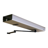
4. For each LAP, use six (6) 1/4-20 x 1/2" Phillips
head screws to secure. (Figure 12)
NOTE:
• Holes in LAP align with threaded holes in
backplate.
• Screws to be torqued to 80 in-lb minimum.
Install Operator
Figure 9
Remaining LAP Mounting Screws - Left Hand View
Figure 11
Figure 10
Left Hand LAP shown
Spring Tube
(at top
of backplate)
6060/6070 @ 85DEG
6060/6070 @90DEG
6060/6070 @ 95DEG
6060/6070 @ 100DEG
6020 & 6060/6070 @ 105DEG
6060/6070 @ 110DEG
6010/6050 & 6030
Operator LAP
Mounting Screws
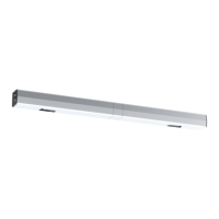
A. Install End Caps.
1. Secure end caps to each end of
connected backplates using four (4)
(two each) #8-32 x 5/16" Phillips pan
head screws. (Figure 9)
NOTE: Orient end caps so that text
on labels is legible when observed
from ground.
Figure 12
 Loading...