Do you have a question about the Assa Abloy PE920 and is the answer not in the manual?
Introduction to ABLOY PE920/PE923 double exit door solutions for electric active door locks.
Overview of product specifications, including door gab guide and general technical data.
Details compliance with EN179 and EN1125 standards, including specific requirements.
Table mapping active/passive door configurations to specific ABLOY models and standards.
Details classifications for EN standards related to fire, EMC, and general door security.
Specific technical details pertaining to the PE951 model.
Visual guides for door drilling patterns required for installation.
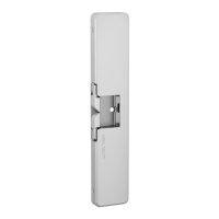
Visual guides for strike plate drilling patterns required for installation.
Comprehensive diagram for drilling the door with specific dimensions and hole placements.
Detailed drilling scheme for specific components and their dimensions.
Comprehensive step-by-step instructions for installing various product components.
Step E of the installation process, illustrating component connections and adjustments.
Step G of the installation process, detailing final adjustments and checks.
Step I of the installation process, detailing component removal or adjustment.
Illustrates correct and incorrect fitting examples to avoid during installation.
Details installation and performance requirements for EN 179 and EN 1125 safety standards.
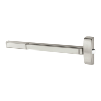
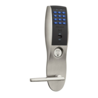
Lists compatible lock brands and models for EN 179 and EN 1125 standards.
Essential safety warnings regarding product modifications and adherence to instructions.
Specifies the operating temperature range for EN 14846 compliance.
Details wiring color codes, lock states, and protection diodes.
Guidance on recycling electronic components and sorting materials.
Statement on the manufacturer's right to make product alterations.
Displays essential safety and compliance marks like CE and DNV.
| Brand | ASSA ABLOY |
|---|---|
| Model | PE920 |
| Category | Door Locks |
| Fail Secure | Yes |
| Voltage | 12/24 VDC |
| Material | Stainless steel |
| Operating Temperature | -40°F to 140°F (-40°C to 60°C) |