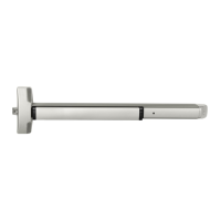
EasyManua.ls Logo

Assa Abloy Yale 6100 Series - User Manual

Assa Abloy Yale 6100 Series
2 pages
Print Icon
To Next Page IconTo Next Page
Loading...
Exit Devices
Copyright ©2015 Yale Security Inc., an ASSA ABLOY Group Company. All rights reserved. Reproduction
in whole or in part without the express written permission of Yale Security Inc. is prohibited.
An ASSA ABLOY Group Brand
6100 / 6200
Series
For technical support contact Yale
®
at
800.438.1951 x5033 or support@yalelocks.com
80-9460-6016-000 10/15
ELECTRIC LATCH RETRACTION
Installation Instructions for
P Function and/or Monitors
Table 1:
Wires from Power Supply to Device
(Minimum Gauge of Two-Conductor Cable)
Up to 40 Feet of Wire 16 Gauge
Up to 60 Feet of Wire 14 Gauge
Up to 100 Feet of Wire 12 Gauge
1. Install the System Peripheral Components (782 Controller, Controlling
Switches, Power Transfer Hinge(s), etc.) and Raceways (Table 1).
IMPORTANT:
Do not connect power until all components are installed.
Integral Power Supply: Connect the wires from the Power Transfer
Hinge, Controlling Switch(es) Console and Power (120 VAC) input to the
782 Controller, as described in the controller installation instructions.
Power Transfer Hinge: Follow the manufacturers’ installation in-
structions. The door leaf wires must exit through the door access
hole, underneath the device rear clamp.
2. Install Device (and optional Trim): Follow the installation instruc-
tions for device (and trim). The Rear Clamp and End Cap are NOT
to be installed at this time.
3. Prepare Wiring Access Hole: Drill a 3/4˝ (19mm) diameter hole in
the door using the rear clamp center hole as a guide (Figure 1).
4. Install the rear clamp screws and fully tighten all device screws.
5. Check Device Action: Actuate the device by the touchbar (and
trim). Be sure that the door and device are operating properly and
that the door is opening freely and closing securely.
6. Connect Device ELR Wires: The red (+) and black (–) polarized
wires from the inactive (hinge) end of the device connect to
DEV 1 on the 782 (see the wiring diagram).
7. Connect Monitors (if used): Follow the connections shown in
Figure 2. Wire nuts are not supplied.
8. Coordinated Door Operation: When two (2) devices are
hooked to the same 782, repeat steps 2. through 7. and con-
nect the second device to DEV 2.
9. Test System: With the power disconnected, verify there are no
short circuits throughout.
Apply power to console (if used) and to integral power supply.
Test the device; bolt should retract when the controlling switch
closes contacts and extend when the switch contacts open.
During momentary or continued operation the device status will
correspond to the switch contact status.
Note:
The 782 Controller has an adjustable delay which causes the elec-
tric latch to remain retracted while the controlling switch is open.
The Troubleshooting Guide (Table 2) provides modifi cations.
Figure 1: Door Preparation
Exit Device Rear clamp
Mounting Holes
(for reference only)
Conducting Hinge
or Approved Power
Transfer (by others)
Inside Face of Door
Clear Channel Access
Required for Wire Connection
3/4˝ (19mm) Dia.
Wiring Access)
Horizontal Reference
Device Centerline
Hinge Edge
of Door
C
L
C
L
Exit Device
4˝ Max.

Questions and Answers

Summary

Electric Latch Retraction Installation

Install System Peripheral Components

Install the 782 Controller, Controlling Switches, Power Transfer Hinge(s), and Raceways.

Install Device and Prepare Wiring

Install the device and trim, drill a 3/4" hole for wiring access, and install rear clamp screws.

Check Device Operation

Actuate the device by touchbar and trim to ensure proper door and device operation.

Connect Device Wiring and Monitors

Connect ELR wires to DEV 1 and connect monitors as shown in diagrams.

Test System and Verify Operation

Test the device after power connection to ensure bolt retraction/extension with switch operations.

Troubleshooting Guide

Device Does Not Work

Troubleshoot issues like device non-operation or latchbolt problems using defined solutions.

Latchbolt Issues

Address problems with latchbolt retraction, sluggishness, or non-retraction.

Intermittent Action

Diagnose and resolve intermittent device operation issues.

Monitor Connections

B Monitor Configuration

Connect B Monitor SPDT switch for egress indication.

O Monitor Configuration

Connect O Monitor SPDT switch for outside door open indication.

S Monitor Configuration

Connect S Monitor SPDT switch for bolt extended/retracted indication.

Overview

This document provides comprehensive installation instructions for the Yale 6100/6200 Series Exit Devices with Electric Latch Retraction (ELR), P Function, and/or Monitors. These devices are designed to enhance security and access control in various applications, offering both convenience and safety features. The installation process is detailed, ensuring proper setup and functionality of the ELR system, which allows for remote unlocking of the exit device.

The core function of these exit devices is to provide secure egress while integrating with an access control system for controlled entry or remote unlocking. The Electric Latch Retraction (ELR) feature is central to this, enabling the latch bolt to retract electrically, typically in response to a signal from an access control system or a remote switch. This allows for hands-free or remote operation of the door, which is particularly useful in high-traffic areas, for accessibility compliance, or in situations requiring quick, automated unlocking. When the ELR is activated, the latch bolt retracts, allowing the door to be pushed open without needing to depress the touchbar. Once the ELR signal is removed, the latch bolt extends, securing the door again.

The "P Function" likely refers to a specific operational mode or set of features related to the ELR, possibly indicating a "Push" or "Panic" function that is enhanced by the electric retraction. This ensures that even with advanced access control, the fundamental panic egress capability remains uncompromised, allowing for immediate exit in an emergency by simply pushing the touchbar. The integration of monitors further enhances the device's utility by providing real-time feedback on the door's status.

Usage Features:

The Yale 6100/6200 Series Exit Devices offer several usage features that contribute to their effectiveness and versatility:

  • Electric Latch Retraction (ELR): This is the primary feature, allowing the latch bolt to be retracted electrically. This enables remote unlocking, integration with access control systems (e.g., card readers, keypads, biometric scanners), and automated door operation. It's ideal for applications where controlled access is needed without compromising emergency egress. For instance, during business hours, the ELR can be activated to keep the door unlocked for easy entry and exit, while after hours, it can be deactivated to secure the door.
  • Integration with Access Control Systems: The devices are designed to seamlessly integrate with a 782 Controller, which acts as the central hub for managing the ELR function. This allows the exit device to respond to signals from various access control components, such as controlling switches, power transfer hinges, and other peripheral devices. This integration provides a comprehensive security solution, enabling centralized management of door access.
  • Monitors for Status Feedback: The inclusion of monitors (B, O, and S Monitors) provides critical feedback on the door's status.
    • B Monitor (Touchbar Actuated): This monitor indicates "Egress in Progress" when the touchbar is depressed. This is useful for security systems to log egress events or to trigger alarms if egress occurs outside of designated times.
    • O Monitor (Device Actuated): This monitor indicates "Door Open from Outside." It's activated when the device detects that the door is open, providing a clear signal for monitoring purposes, such as detecting forced entry or simply confirming the door's state.
    • S Monitor (Slider Actuated): This monitor indicates whether the "Bolt(s) Extended - Retracted." This provides direct feedback on the latch bolt's position, confirming if the door is secured (bolt extended) or unlocked (bolt retracted). This is crucial for verifying the ELR's operation and the overall security status of the door.
  • Coordinated Door Operation: For installations with multiple devices on the same door or in close proximity, the system supports coordinated operation. When two devices are connected to the same 782 Controller, their ELR functions can be synchronized, ensuring consistent and reliable operation across multiple points of egress.
  • Adjustable Delay: The 782 Controller features an adjustable delay, which allows the electric latch to remain retracted for a specified period even after the controlling switch is opened. This provides flexibility in managing door access, ensuring that individuals have sufficient time to pass through the doorway before the latch re-engages.
  • Emergency Egress: Despite the advanced electronic features, the fundamental panic egress function remains paramount. In an emergency, pushing the touchbar will always retract the latch bolt, allowing for immediate exit, regardless of the ELR status or power supply. This ensures compliance with life safety codes.

Maintenance Features:

While the document primarily focuses on installation, several aspects imply ease of maintenance and troubleshooting:

  • Troubleshooting Guide: A detailed "Troubleshooting Guide" (Table 2) is provided, offering solutions for common issues such as "Device Does Not Work," "Latchbolt(s) Are Not Retracting," "Sluggish Bolt Retraction," and "Intermittent Action." This guide is invaluable for diagnosing and resolving problems efficiently, reducing downtime and the need for specialized service calls. The solutions range from checking remote switches and circuit continuity to inspecting wiring and looking for foreign materials.
  • Clear Wiring Diagrams: The installation instructions include clear diagrams for door preparation and monitor connections, which simplify the initial setup and aid in future troubleshooting. Well-documented wiring helps in quickly identifying and rectifying connection issues.
  • Accessible Components: The design suggests that components like the rear clamp and end cap are installed after initial wiring, potentially allowing for easier access to internal wiring for inspection or repair if needed. The 3/4" (19mm) diameter wiring access hole ensures sufficient space for wire routing and connection.
  • Component-Based System: The system is built with distinct components (782 Controller, power transfer hinges, monitors, exit device), which can simplify maintenance. If one component fails, it can often be isolated and replaced without affecting the entire system, leading to more targeted and cost-effective repairs.
  • Pre-Installation Checks: The instructions emphasize pre-installation checks, such as verifying that the door swings freely and that the manual device action works properly. These checks help prevent issues that might arise from improper door alignment or existing mechanical problems, contributing to the longevity and reliable operation of the ELR system.
  • Power Disconnection for Testing: The instruction to disconnect power before testing for short circuits is a crucial safety and maintenance practice, preventing damage to components during diagnostic procedures.
  • Wire Gauge Recommendations: The "Wires from Power Supply to Device (Minimum Gauge of Two-Conductor Cable)" table (Table 1) provides specific wire gauge recommendations based on distance. Adhering to these recommendations ensures proper power delivery and signal integrity, which is vital for the reliable operation of the ELR and helps prevent issues related to voltage drop or overheating, thereby extending the life of the electrical components.

In summary, the Yale 6100/6200 Series Exit Devices with ELR and monitors offer a robust and intelligent solution for door security and access control. Their design prioritizes both advanced functionality and ease of maintenance, ensuring reliable performance and straightforward troubleshooting.

Assa Abloy Yale 6100 Series Specifications

General IconGeneral
BrandYale
ManufacturerAssa Abloy
CategoryDoor Locks
TypeMortise Lock
Door Thickness1-3/4" to 2-1/4"
Backset2-3/4"
SecurityHigh Security
KeywayYale Keyway
HandingReversible
Series6100 Series

Related product manuals