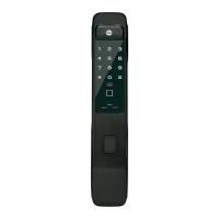
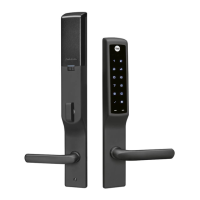
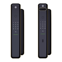
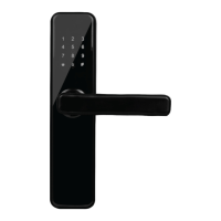
This document provides installation instructions for the Yale Delayed Egress Exit Device, covering various models including Rim, Mortise, SquareBolt®, Concealed Vertical Rod, and Surface Vertical Rod (which requires rod guards from other manufacturers). The manual emphasizes the importance of proper installation, especially concerning fire-rated openings, and advises consulting with a code specialist or local code official to ensure compliance with all applicable codes and ratings.
The installation process begins with a checklist to ensure all parts are present and undamaged, and to identify the device's options, model, type, and trim hand. The manual then details the required components, which include the Delayed Egress Exit Device itself, a 24VDC UL Listed Regulated and filtered Power Supply with Fire Alarm Interface (not for use in UL603 Burglar Alarm Systems), a UL or ULC listed power transfer (Securitron EPT or equivalent), and a "PUSH UNTIL ALARM SOUNDS. DOOR CAN BE OPENED IN 15 SECONDS." sign, which must be installed on the door above the device. The delayed egress system must be installed in accordance with NFPA 101.
Optional components are also listed, such as a remote annunciator, door position switch (DPS), standard trim, electrified trim, and device and trim cylinders. The electrical specifications indicate an input voltage of 24VDC (+/-10%), with wire sizes of 18 AWG Min (up to 100') for power and 22AWG Min for signal or control. Power consumption varies: 500mA for a standard device, 750mA with a security package, and 1.25 amps with electric trim. Local electrical codes for wiring must be followed.
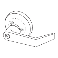
The manual provides detailed instructions for the End Cover and P.C. Board Assembly. This section covers trimming the device to the proper length (1" maximum for 36" exit devices, 6" maximum for 48" exit devices), carefully sliding the circuit board assembly into the end cover to avoid bending the indicator light (LED), and inserting the mortise cylinder with the keyway horizontal. It also explains how to slide the arming switch activator over the mortise cylinder, insert the flange of the cylinder nut into the arming switch activator, and tighten the cylinder nut to secure the circuit board assembly. A crucial verification step involves rotating the key counter-clockwise and clockwise to ensure it moves freely and the arming switch trips in both directions. Adjustments to the activator legs are suggested if the arming switch does not trip correctly.
The installation of the end cover assembly to the device includes setting nuisance delay (J5) and reset delay (J8) jumpers. Jumper on for J5 sets a 3-second nuisance delay (default), while jumper off sets an immediate alarm. For J8, jumper on sets a 10-second reset delay (default), and jumper off sets a 20-second delay. The end cover assembly is then slid into the exit device, taking care not to pinch or crimp wires. The device lock assembly is connected to Connector J1, and excess wires are placed between the end cover and circuit board.
For ElectroLynx Connector Systems, the manual outlines mounting the exit device, plugging the exit device connector into the raceway connector, and plugging the raceway connector from the edge of the door into the electric hinge connector. It provides options for wiring immediately or later, emphasizing that wiring to the pigtail harness is per facility requirements. The ElectroLynx system is designed for easy installation with plug connectors from the electric hinge through the door to the device, and connectors are designed to mate and lock together without force.
For non-ElectroLynx doors, the connector at the end of the exit device is removed and connected to incoming wires from the power source using wire nuts or butt splices. The manual includes a wiring layout and jumper settings, detailing the functions of various wires such as remote bypass, remote reset, secure relay output (NC/NO), and alarm relay output (NO/NC). Pins 5-8 are negative outputs for LEDs and audibles. All unused wires should be capped with enclosed wire nuts.
Door preparation for non-ElectroLynx systems is also detailed, with dimensions provided in inches and millimeters. The instructions highlight that this preparation is an addition to the device template and advises locating and preparing wiring access holes during installation. Shields for wiring access are recommended for insulated and composite doors.
The wiring diagram for a single door exit only illustrates the connections between the exit device, wire transfer hinge, and a Securitron BPS power supply with fire alarm interface. It also includes connections for trigger switches, lock, power, DPS, and ground.
Wiring options are provided for various scenarios, including electrified trim (fail safe or fail secure), mechanical trim entry with a security package (Rim and SquareBolt), and mechanical trim entry with an external door position switch. The security package activates an alarm if the door is forced open and prevents the device from arming if the door is propped open. If an "O" trim monitor switch is activated, it bypasses the unit, allowing entry, and the unit must be manually reset for rearming.
The operating instructions describe three modes: Delayed Egress, Momentary Egress, and Bypass (Maintained) Egress.
- Delayed Egress Mode: After applying power, a solid red LED illuminates, indicating the device is armed and will not allow immediate latchbolt retraction.
- Momentary Egress Mode: With the device armed, rotating the key counter-clockwise and returning it to the center position (removing the key) causes the red LED to flash quickly. The device releases for momentary egress for 10 seconds (default, 20 seconds if J8 jumper is removed). After this time, the device rearms.
- Bypass (Maintained) Egress Mode: Rotating the key clockwise and returning it to the center position (removing the key) causes the red LED to flash slowly. The device is disarmed, functioning as a standard exit device with free egress.
- Resetting from Bypass Mode: Rotating the key counter-clockwise and returning it to the center position (removing the key) causes a solid red LED to illuminate, returning the device to delayed egress mode.
The Delayed Egress Operation When Armed section explains that the device secures the door with a solid red LED. Depressing the pushpad for two seconds or less triggers a nuisance beep. Depressing it longer than three seconds initiates an irreversible local audible beeping tone and a visual amber indicator. After a delay (15 or 30 seconds), the LED changes to green, the siren changes to a steady tone, and the device releases for exit. Remote monitoring contact outputs can alert security personnel. The manual notes that a BOCA option is required for a 30-second delay and auto reset, and advises consulting the authority having jurisdiction for local code requirements.
Additional options include the Security Package (H Suffix) for 7100 Rim and SquareBolt devices, which includes a door position switch in the active case head assembly, preventing arming until the door is closed and latched, and activating an alarm if tampered with or forced open. Electric Trim (Safe/Secure) for Mortise Devices offers fail-safe (SAF) or fail-secure (SEC) outside trim operation. If a Door Position Switch is not used, the trim will open the door without affecting the device in an armed condition. The Outside Trim Monitor Switch (O Suffix) allows the trim to be used with a security package or external DPS for bypass (disarming the device) during ingress, requiring a reset via keyswitch or remote SPDT switch. The Latchbolt Monitor Switch (S Suffix) is a SPDT switch that monitors the security of the latchbolt or vertical rods. The BOCA Option (C Suffix) allows the device to release after 30 seconds when force is applied to the pushpad, providing visible and audible indication, and automatically re-locks and rearms after the door has been opened.
Finally, a troubleshooting guide addresses common issues such as the unit not arming (no red LED), continuous alarming, issues with security packages (Rim and SquareBolt) or door position switches (CVR or Mortise), mechanical latchbolt retraction with power applied and LED armed, and improper latchbolt/rod latching. Solutions involve checking connections, power supply (24VDC regulated, correct amperage), trigger mechanism, pushpad activating switch, strike magnet alignment, and DPS wiring. If troubleshooting fails, contacting the local hardware distributor, Yale representative, or Yale directly is advised.