13
q C1, LC1 470uF 16V (Sig)
q C2, LC2 220uF 160V
q C4, LC4 100uF 100V (Sig)
q C5,6, LC5,6, 10uF 450V
q C300 10uF 450V
q C100,101, LC100,101, 4700uF 16V (Sig)
q C400 4700uF 16V
q C200A,B 100uF 400V On Main Filter Bank
q C201A,B 470uF 400V On Main Filter Bank
q C202A,B, LC202A,B 220uF 400V On Left & Right CH Filter Banks
Capacitors - Film, etc.:
q CC1,2,3 .1uF 50V
q C3, LC3 .22uF 600V *** Keep these cut leads for
later use *** (Sig)
q AC1 .1uF 275VAC On AC SW PCB
Switch:
q SW1 DPST Push-On Push-Off switch for AC SW PCB
Miscellaneous Parts:
Wiring:
F rom the backside of the PC board, filament power needs to be
j u m p e red over to V1 from V3. Note the pair of enclosed pads that are
just above the two tube sockets. Look for the markings labeled “A >”,
and “< A”. These pairs of pads need to be connected together with
the green wires, and you need not worry about the polarity because
this is an AC filament voltage.
q G reen 18awg 7.75” (200mm) x 2
q Cut 2 pieces of 18awg Green wire 7.75” (200mm) long and ‘pre p a re ’
both ends for soldering.
q F rom the back of the PC board, insert and solder the pair of wire s
into the empty pair of pads at V1.
q Twist these wires tightly together to take up the slack and then insert
the free ends into the pair of pads closest to V3.
N o t e : Do not thread this wire between the tube socket standoff and
its pins. The tube input grid pin 1 is too close for comfort here .
q As you solder these into place check that you put them into the
g rouped pads labeled “<A”.
q F rom the top of the PCB, trim the excess wires at both V1 and V3.
LED Indicator Light:
Because the distance from the PC board to the mounting hole in the
f ront of the main chassis/faceplate is greater than the length of the
LED leads, wire extensions must be soldered to the LED leads. Use
two resistor leads left over from the installation of the resistors. Tw o
1”(25mm) lengths are sufficient. Heat shrink tubing is then used to
cover and isolate the leads from any chance of a short circuit. This is
v e ry important because the LED is supplied by the V1 & V3 filament
s u p p l y, which is biased up to a high DC voltage potential, which saves
the tube cathode from self-destruction. Then the LED leads are bent
to enable it to be mounted into the front panel hole.
q LED1 Coool Blue LED power indicator x 1
q cut leads x 2
q 1/8” heatshrink tubing 1 5/8”(42mm) x 2
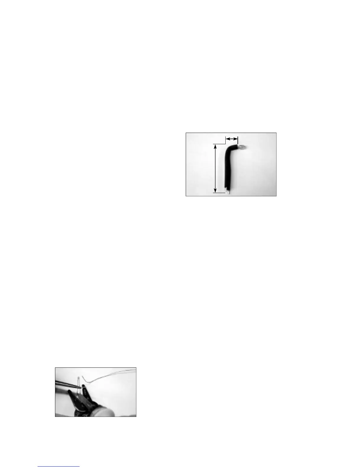
q Attach the two extension leads to the LED leads by first holding the
LED leads with a pair of needle nose pliers. See the photo please.
This is very important to do because the heat being applied while
soldering on the extensions can easily destroy the LED! We need to
keep this ‘coool blue’ LED cool!
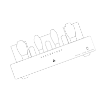
The total lead length needs to be at least 1 7/8” (47mm) long.
q Cut 2 pieces of 1/8” heatshrink tubing 1 5/8”(42mm) long.
q Slide the heatshrink tubing over the LED leads up to the LED body
and shrink it into place by heating the tubing with the soldering iron or
a hot air gun.
q Next we will bend the LED at a right angle according to the picture .
Pay close attention to the flat side of the LED body. LED’s are polarity
demanding. Align the LED flat side with the PCB screening. If your
LED does not have a flat side, then be sure that the long lead, or the
ANODE, connects to the round pad on the PCB, or the pad labeled
“ A ” .
q Put the LED aside for now because it will be easier to mount it later
after the PCB is installed.
This now completes the soldering of the PC boards. Just before you
take a break and admire your handy work... Go back and double-
check all your work. You know, look for the presence of solder bridges,
cold solder joints or missed solder joints, stray pieces of wire, leads
not trimmed, and check that all components are inserted corre c t l y
with re g a rds to polarity.
This is a good time to sample your favorite re f reshments or get some
f resh air.
Bottom Cover & Main Chassis Assembly:
Welcome back. Next we will work on mounting of the feet, IEC socket,
RCA jacks, speaker binding posts, mute switch, and whatever other
p a rts or components that I can’t think of now that needs to assemble
to the chassis itself at this time.
Anxious to get going I know, but lets protect your investment a bit first.
Clean your work area from any foreign objects that may scratch the
chassis or transformers while they are on their back. You may want to
place a soft cloth or towel on your working surface to provide a safe
padded working enviro n m e n t .
Bottom Cover
Feet:
This simple step will get us off to a running start you might say. The
four rubber feet can now be fitted to the cover for the bottom of the
c h a s s i s .
q Rubber Feet x 4 (Sig)
q 6-32 x 3/4” Philips screws x 4
Using the 6-32 3/4” screws, bolt the feet in place in each corner of the
bottom cover. CUE: The feet will lie flat or will be flush to the surf a c e
of the cover when mounted corre c t l y.
q Put this cover aside for now we will need it later.
Main Chassis:
Place the chassis right-side-up in front of you on your clean scratch-
p roofed surf a c e .
1
7
/1 6”
5
/1 6”
 Loading...