1718
q M3 10mm (3/8”) Blk CS screws x 2
q Solder lug x 1
q 6-32 1/4” Zinc Philips screw x 1
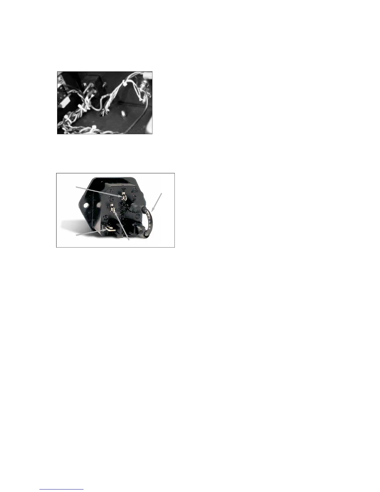
< I n s e rt IEC wired photo>
q P re p a re the list of wires and heatshrink tubing to the lengths above.
P re p a re the wire this time by stripping 1/4” (6.5mm) of the jacket off
the ends.
q Following the photo captions, attach the Black wires ‘A’ and the
G reen wire ‘B’ to the terminals labeled ‘L’ and the center bottom
t e rminal, the ground, re s p e c t i v e l y.
q Try to insert the wires into the holes in the IEC terminals and crimp
or wrap the wire around the terminal before soldering.
q Slide the heatshrink tubing onto the black wire only and shrink it over
the term i n a l .
q The 2” black wire is used to link the fuse terminal to the “L” term i n a l
on the back of the IEC module. Slide two pieces of heat shrink tubing
on the link, 1 for each end. The “L” terminal now becomes the bottom
left terminal in this Photo.
q F rom the outside, install the IEC module into the chassis with the
fuse drawer towards the bottom of the chassis.
q Simply bolt in place using the supplied M3 scre w s .
q Next screw the solder lug to the chassis standoff next to the IEC
module.
q The green wire from the IEC module will be soldered to this lug now.
No heatshrink tubing is to be used on this connection. Loop the wire
t h rough the solder lug hole, crimp and solder.
Main Chassis Assembly
Now we can start mounting and connecting the remaining hard w a re
like the choke, transformers and the PC boards, and finish off the
re q u i red wiring. Lets transform this basic black pizza box into an
a m p l i f i e r !
Choke Mounting:
In the main power supply of this 300B amplifier we use a choke or
inductor plus capacitors in a pi filter arrangement. This AC ripple filter
works very efficiently in purifying the high voltage. This Choke is
mounted inside of the chassis. We will also pre p a re the leads for easy
installation to the Main Filter Bank PC board .
q #8-32 1/2” Philips screws x 2
q #8-32 kepnuts x 2
q 4H Choke Inductor x 1
q B e f o re you jump the gun and install this piece of iron, we will dre s s
the leads. Tightly twist the black and white wires and trim them to 4.5”
(115mm) long and tin the ends.
q Relocate the choke mounting hard w a re that you put aside (#8 nuts
and screws), and relocate the two mounting holes in the center rear of
the chassis.
q OK now the choke is installed such that the wires exiting its end bell
a re facing towards the left side or the IEC module.
q I n s e rt the screws from the outside of the chassis, and tighten down
the kepnuts for the inductor into position with an 11/32” nut-driver
while holding the head of the screw with a Philips scre w d r i v e r.
Power Transformer Mounting:
The custom power transformer is the single transformer with the most
w i res coming out of it. It is mounted from the top of the chassis and it
needs to be properly oriented. Once installed all the primary and
s e c o n d a ry wires will be cut and groomed to be neat as possible.
q Power Tr a n s f o rmer x 1
q #10-32 3/8” Blk Philips x 4
q #10 Split lock washers x 4
q Now that you have such a nice clean soft working surface, lets test
it out. Check for any foreign materials that may cause scratches to the
chassis top surface.
q For greater ease of this next assembly sequence, flip the chassis
over onto its right-side-up position. No kidding you say.
q We need to arrange this transformer position so that the primary
winding wires coloured, brown, orange, white, and black, etc., all face
t o w a rds the RIGHT Channel or the IEC module.
q With this relationship in mind, gently place the transformer on its
side on top of the chassis, on top of where the tube sockets will be.
q Feed the Primary and Secondary wires down through the larg e
access holes into the chassis cavity. Lift the transformer up and onto
its mounting location when you have fed enough of the wires thro u g h
to allow this to happen. CUE: Watch out for pinched wire s !
q Using the #10-32 screws and lock washers, secure the power
t r a n s f o rmer to the top of the chassis.
Output Transformer Mounting:
The custom output transformer pair is also mounted from the top of the
chassis and they need to be properly oriented as well.
q #10-32 3/8” Blk Philips x 8
q #10 Split lock washers x 8
q Output Tr a n s f o rmers x 2
q We need to arrange these transformers’ position so that the primary
winding wires coloured red and blue are entering the access holes
closest to the front of the chassis.
q While holding the O/P transformer above its mounting position, feed
the wires down into the appropriate access holes and then place the
t r a n s f o rmer down onto the chassis.
q Using the #10-32 screws and lock washers, secure both of the O/P
t r a n s f o rmers to the top of the chassis.
This is now the end of the grunting section. Chassis assembly is
always involving the heavy work. Lets put aside our macho bro n z e
and re-apply our brains.
A quick check of what we have just installed would be in order now. It
is easy to correct anything at this stage; no E.C.N.’s needed here .
Check the following:
q A re the SPEAKER BINDING POSTS arranged with the RED term i n a l
t o w a rds the TOP of the chassis, or away from you? A little “+” sign will
also be adjacent to this RED post.
q Is the IEC AC input module positioned such that the green wire is
away from you closer to the TOP of the chassis, which ‘looks like’ the
bottom from here ?
q The POWER TRANSFORMER RED wires need to be to the RIGHT
side of center.
q The OUTPUT TRANSFORMER secondary end with the bundle of six
(6) wires must be to the REAR of the chassis.
q A re the wires from the CHOKE on the LEFT side?
Good work, lets move on. That is of course that you are ready for the,
‘not difficult’, but demanding task of correctly wiring this amplifier.
Live
wire A
B l a c k
N e u t r a l
Link
wire C
B l a c k
G ro u n d
wire B
G r e e n
 Loading...