25
of the amplifier to keep it from tipping forw a rd .
q Now that all the circuit board assembly and wiring has been verified
to be correct, select the 2.5 amp “slo-blo” fuse and install it into the
fuse holder. Open the drawer of the IEC AC module and clip it into the
back area compartment of the drawer and close it again. For
220/240V operation, use the supplied 1.25A “slo-blo” fuse.
q Make sure the power switch is in the “OFF” position. Plug the
detachable power cord into the AC socket at the back of the amplifier.
If you have access to a variable AC transformer (VARIAC), plug the
c o rd into it. If not, plug the cord into the nearest AC wall outlet.
q Tu rn the amplifier on. The Coool Blue LED should light. Tu rn OFF the
amp again.
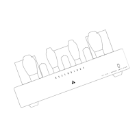
q Select the 6SN7GT and plug it into the center front socket.
q Select the 6BX7GT’s and plug them into the other front sockets.
Each box is identified with a ‘L’ or ‘R’ for Left or Right channel
installation. CUE: The chassis is clearly labeled as to which tube goes
into each socket.
q Tu rn the amplifier on again. Check that these tubes light up norm a l l y
plus the LED. The 6BX7’s will glow brightly. Tu rn OFF the amplifier
a g a i n .
q Plug in the 300B tubes into their sockets and test for a warming of
the tube when you apply power. It may be difficult to see the filaments
glowing in these tubes. Tu rn OFF the amplifier again.
q Lastly install the CV378’s. These are the high voltage rectifiers so
please be aware that now after about 20-30 seconds there may be
f i reworks in your faulty amp or if not that, there will be dangero u s l y
high voltages inside the chassis on all the circuit boards. Keep your
fingers to yourself please.
q Tu rn the amplifier ON and watch for smoke signals, and if all goes
well, after 3 minutes shut it OFF again.
q Unplug the power cord. Wait 5 minutes before touching anything
inside of the chassis.
q The trimmer pot will not likely need to be adjusted. It is there to
balance the AC ripple from the power supply across the 300B. This
will minimize the amount of hum that you may hear on your speakers.
If you want to try adjusting it, you could look at the amplifier O/P with
a scope or listen closely to your speakers to null the hum out. CUE:
Another method you may try to reduce the low-level hum is to re v e r s e
the two red wires of the high voltage windings. Need I say that you
must unplug the power cord before changing these wire s ?
Last Step:
q This is the last step, install the bottom cover with the twelve black
6-32 1/4” Philips screws. The vents are positioned towards the front of
the chassis.
q At this time it appears that you are ready to introduce your new
S E T-300B into its new home. I trust that you will not need more
i n s t ructions on how to install the unit in your system.
In Closing:
It has been a pleasure working with you during the construction of this
p roject. Likewise, I hope that the experience has been a pleasant one
for you as well. TPC and I believe that you will enjoy your new
Assemblage SET-300B Amplifier for many years to come. Please feel
f ree to call or write us to let us know any of your comments on this
p roject, good or bad. Your input is valuable to us to continue to supply
you, the D.I.Y. e r, with the best possible kits available on the market
today and tomorro w. Take care and Happy Listening.
Trouble Shooting:
Gee, it looks like you are going to need to go that extra mile, and I am
s o rry that your unit is not up and running perfectly at this point. Don’t
despair because all of TPC is behind you, and we will get you going
with the minimum amount of grief.
Please do a recheck of the list above found in “Final Check and
A d j u s t m e n t : ” .
If you are technically inclined, you may refer to the schematic drawing
on pages 14-15, where you will find a ‘DC TEST VOLTAGE’ chart .
C o m p a re these voltages with the readings that you obtain in your
a m p l i f i e r. The PCB has all of the Test points clearly marked for your
convenience. Record these readings and if you are having diff i c u l t i e s
solving the problems with your amp, we are here to take you step by
step through the unit to get it working. Give us a call or write us via fax
or email detailing your contact information and amp symptoms
including the voltages at all the test points.
B a rring that, simply arrange to re t u rn it to us and we will get it going
for you. May I wish you then a belated Happy Listening!
 Loading...