19
Chassis Wiring (Part 1):
In this section we will connect the output transformers and set the O/P
load impedance to 4,8, or 16 Ohms, configure the power transform e r’s
p r i m a ry windings for your AC line voltage, then connect and install the
AC SW PCB.
q Black 18awg hookup wire 10.5” (267mm) long x 1
(For Stereo configuration)
q Black 18awg hookup wire 11.5” (292mm) long x 1
(For Mono Block configuration)
q Black 18awg hookup wire 1 2” (305mm) long x 1
q 3” Cable Ties x 2
q Twist style Connector x 4
Output Transformer Wiring/Configuration:
First the 300B plate connection to the output transformers will be dealt
w i t h .
q The RED wire from the transformers need to be trimmed to a length
of 5.75”(146mm) measured from the chassis opening.
q Strip this silver-plated copper, teflon jacketed leads to 1/4” (6.5mm).
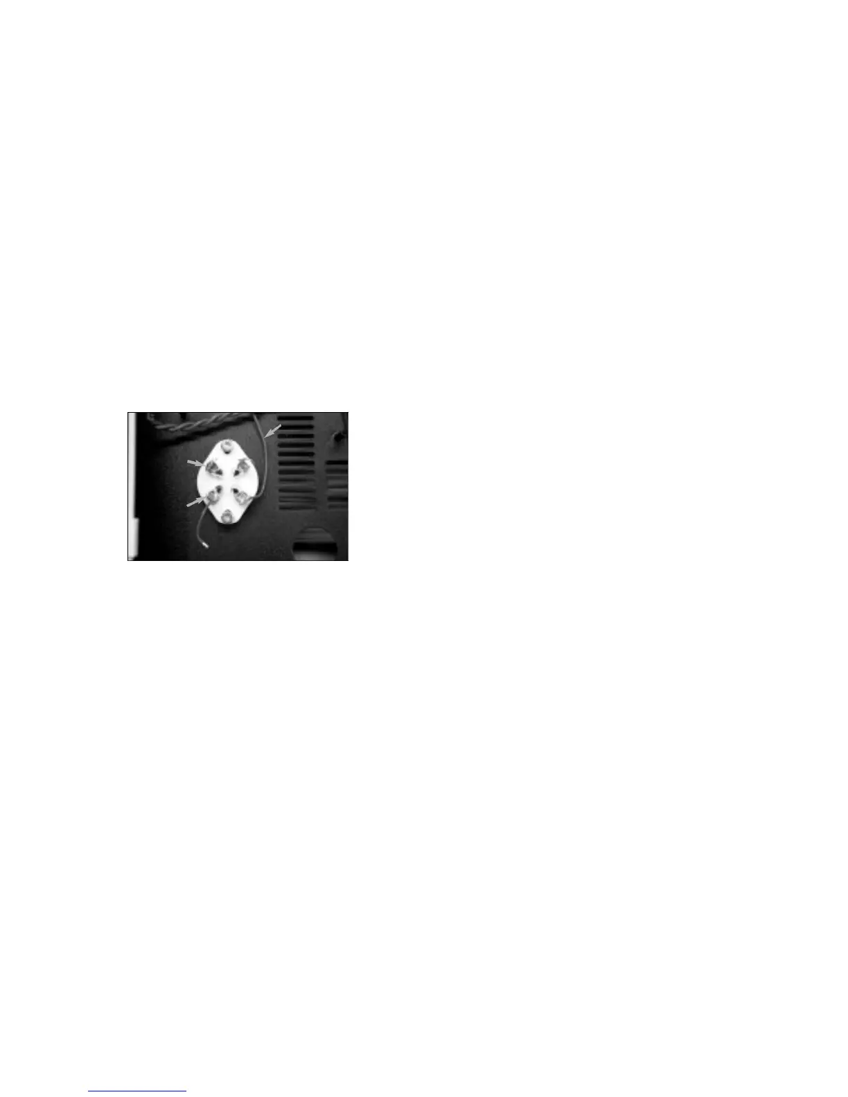
q Looking from the top of the 300B tube socket, attach this RED lead
to the bottom right pin. CUE: Look for the right hand small hole in the
socket which is the closest to you as you are working from the front of
the chassis. Wrap and crimp the wire into place and then solder. Do
both channel sockets the same way. Please check the photo for
p roper pin ID if in doubt, this socket does not have pin numbers on it
to aid you here .
The following blue wires are the high voltage connections for the
output transformer and there f o r e the 300B’s. These will be connected
to the Main Filter Bank at a later time, but we will get them ready now.
Note that each wire is a diff e rent length, if you wish it to be.
q P re p a re the BLUE wire of the LEFT CHANNEL O/P, which is the
Right side as you are looking at it from the top, to a length of 7 1/4”
(185mm).
q Now pre p a r e the other BLUE wire for the RIGHT CHANNEL, which
is the Left side as you are looking at it from the top, to a length of 5”
(127mm). For all of you really fussy D.I.Y. e r’s, make this wire the same
length as the left channel, (7 1/4”). I have tried to keep perf e c t
s y m m e t ry wherever possible in this design.
Mono Block operation or Stereo operation?
Two B or not two B, that is the question. The option is yours, do you
want two SET- 3 0 0 B ’s per channel driving your speaker cabinet, or do
you want one SET-300B per channel to drive your speaker cabinet? To
put it another way, do you want a Mono Block setup with 16 watts of
power for your one speaker cabinet, where you will need two amp
c h a s s i s ’s for stereo, or are you going to run a single Stereo amplifier
chassis with 8 watts O/P per channel, to drive your pair of speaker
c a b i n e t s ?
Hence, if you are running the standard Stereo chassis skip down to
the heading - ‘Stereo Operation’.
Mono Block Operation:
Now here is a feature that will make some of you very happy! For those
of you who would prefer to run your SET-300B as a mono block, this
next setup is for you. (Remember of course, that for a stereo or multi-
channel setup you do need a SET-300B mono block for each audio
channel running.) The power increases from 8 watts to 16 watts in this
mode as well.
The format here is that we will connect the two audio channels
together at the input and apply your input signal to either I/P RCA jack.
The doubling of power will be developed by configuring the output
t r a n s f o rmer windings in series with each other. The speaker will then
be connected from the ‘-’ of the Right channel speaker post, to the ‘+’
of the Left channel speaker post. One last point to consider - if you
want your output speaker impedance set to 8 ohms, the two individual
t r a n s f o rmer windings need to be set for 4 ohms operation. Eight ohm
t r a n s f o rmer setup is there f o re needed if your speakers are 16 ohm
i m p e d a n c e .
A permanent signal common re t u rn wire must be connected to the
“-” speaker binding post of the Right channel and another that
i n t e rconnects the “+” post of the Right channel to the “-” post of the
Left channel before the transformer secondary wires are attached.
When reconfiguring for diff e rent speaker loads, you will not be
changing these connections.
q Cut and pre p a re one 12”(305mm) length of Black 18awg hookup
w i re. One end treated as per the usual and the other gets stripped to
3/4” (19mm), tin them both.
q Cut and pre p a re one 11.5” (292mm) length of Black 18awg hookup
w i re. Both ends gets stripped to 3/4” (19mm), tin them both.
q I hope that your soldering iron is good and hot because it will need
to be to connect these wires to the terminals of the speaker posts.
q READ CAREFULLY: In the groove at the end of the “-” speaker post
of the Right channel, the ‘long end’ of this wire is snugly wrapped,
then, snugly again back around itself to form an “eyelet” shape. Tw i s t
this eyelet so that it is tight. We don’t want this connection to be
disturbed in the future when you may want to re c o n f i g u re the O/P for
a diff e rent speaker load.
CUE: If you approach the post from the center of the chassis, the wire
will line up better for its connection to the center of the Main PC board .
Connection of the free end will be left until the Main circuit board is
installed into the chassis.
q Connect the 11.5” wire to the “+” post in the same fashion.
q The other end of this wire is then similarly connected to the “-”
t e rminal of the Left channel speaker post.
q Lightly tin the “+” speaker post to get it ready for the wire
connections to come.
The next step is to configure the Output transformer secondary
windings for the proper speaker load. Remembering what I said
above, look below in the ‘Stereo Operation’ section for the wiring
configurations for your application, and also follow the ‘General
I n s t ructions’ below to make your connections to the binding posts
t h e m s e l v e s .
Once this is done please advance down to ‘Chassis Wiring (Part 2)’.
Stereo Operation:
The following construction steps are to be followed if you are using
your SET-300B amplifier in a - standard two channel in one chassis or
s t e reo chassis operation.
A permanent signal common re t u rn wire must be connected to the “-
” speaker binding posts before the transformer secondary wires are
attached. When reconfiguring for diff e rent speaker loads, you will not
be changing this connection.
q Cut and pre p a re one 12”(305mm) and one 10.5” (267mm) lengths
of Black 18awg hookup wire. One end as per the usual and the other
gets stripped to 3/4” (19mm), tin them all.
q I hope that your soldering iron is good and hot because it will need
to be to connect these wires to the “-” terminals of the speaker posts.
q The 12” wire will connect to the Left channel “-” binding post, and
the 10.5” wire will connect to the Right channel “-” binding post.
q READ CAREFULLY: In the groove at the end of the “-” speaker post,
the ‘long end’ of this wire is snugly wrapped, then, snugly again back
a round itself to form an “eyelet” shape. Twist this eyelet so that it is
tight. We don’t want this connection to be disturbed in the future when
you may want to re c o n f i g u re the O/P for a diff e r ent speaker load.
CUE: If you approach the post from the center of the chassis, the wire
will line up better for its connection to the center of the Main PC board .
Connection of the free end will be left until the Main circuit board is
installed into the chassis.
q Lightly tin the “+” speaker posts to get it ready for the wire
connections to come.
red wire
f r om output
t r a n s fo r m e r
small holes
l a rge holes
 Loading...