1516
Transformer Removal:
B e f o re proceeding any furt h e r, remove the transformers from the
chassis. This may make life a whole lot easier and avoid the chance
of damaging or scratching the transformers.
Why remove them you say, are n ’t we trying to assemble this thing? Ye s
we are but for one, they may be in backwards, and they will get in our
way for now. So out they come.
q U n s c rew the screws holding the transformers in place - remove the
output transformers first! Then the power transformer can be
removed. Set all the transformers aside where they won’t get in the
w a y, we will, actually you will reinstall them later.
Now we may place the chassis up-side-down in front of you, again on
your clean scratch-proofed surf a c e .
Choke Inductor:
Still in the mood for disassembly? Guess what gets removed now? If
you guessed the power supply filter choke, you where right. Do so
and put it aside for later. Put the nuts and screws in a safe place as
w e l l .
Speaker Binding Posts:
Install the speaker binding posts, (yes I did say install), such that the
red post lines up with the “+” screening on the rear of the chassis, or
t o w a rds the top of the chassis, and the black post lines up with the
“-” screening on the rear of the chassis. Use the supplied washers
and nuts, and ensure that the posts are attached tightly to the chassis.
(5/16” nutdriver)
NOTE: Be aware that the individual post itself sits into a key-way in its
mounting housing.
q Dual 5-way Binding Posts x 2 (Sig)
Be pre p a red, we are now entering into some of the more delicate
assembly pro c e d u res involved with this SET-300B construction kit.
300B Tube Sockets:
H e re is an easy warm-up to what is to come. The 300B tube sockets
a re to be correctly oriented, mounted to the chassis openings. The
nylon shoulder washer will cushion the ceramic socket from the
abrasive and crushing kepnut.
q Ceramic wafer socket x 2
q #6 nylon washer x 4
q #6 Kepnut x 4
q View the top of the socket and notice that all the pin access holes are
NOT all the same size. There is a pair of large and small holes.
q Slide the socket over the two mounting studs flanking the two larg e s t
chassis cutouts.
Be sure that the largest pair of socket holes are to the rear of the
chassis! Please be sure to get this correct, because there are no other
pin identifications on this ceramic wafer socket.
q Install the nylon washers over the studs, and then the #6-32 k e p n u t s .
q Snug up the nuts, there is little chance that the socket will be
damaged, because of the compliant nature of the nylon washers.
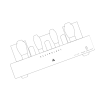
q To pre p a re the socket pins for the installation of the Main PC board ,
we will now bend the solder lugs of these terminals inward toward the
center of the socket. See the photo for the finished look. CUE: Place
the MAIN PCB over the socket to see if the socket pins clear the
edges of the circuit board cutout.
q Repeat this pro c e d u re for the other 300B socket.
B e f o re A f t e r
RCAInput Jacks:
Install the RCA jacks, making sure that the insulating washers are
c o rrectly saddled within the chassis holes. The solder lugs will need
to be positioned properly for future connections and likewise for the
jack.
Right I/P
q RCA female jack with RED band x 1 (Sig)
q Red is for the Right channel I/P. Note the screening label “R” on the
chassis rear panel, indicating the Right channel I/P.
q F rom the inside working outwards, place the solder lug on the jack,
then the nylon shoulder washer.
q Place these into the chassis hole from the re a r.
q Apply the flat nylon washer and then the nut from the outside.
(12mm nutdriver or wre n c h )
q Notice that the RCA jack signal terminal is notched. Align this notch
to face upwards towards you and while tightening the nut hold the
solder lug so that it points straight over to the opposite RCA jack.
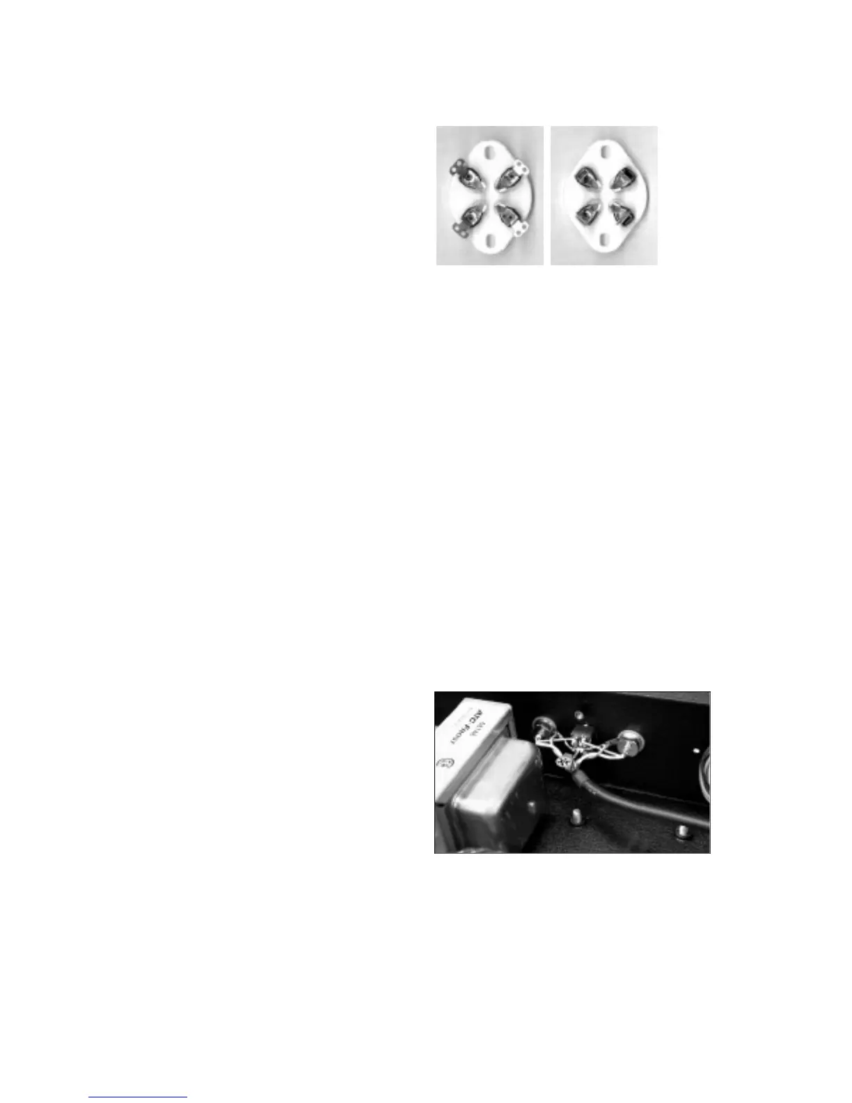
q One more finer detail, bend the solder lug out to 45 degrees fro m
the chassis. Check out the photo to ensure you get a clear picture of
this setup. You will be soldering to this lug later and we need good
access to it and this will also help to ensure that the wire lead
mounting into this hole will not come in contact with the rear chassis.
Left I/P
q RCA female jack with WHITE band x 1 (Sig)
q White is for the Left channel, I am sure you know where this one
goes, go for it.
q This time the solder lug again points towards the opposite RCA jack
Mute Switch:
Having a mute switch is one of the nice features of this kit. The vert i c a l
travel of the long bat handle makes it easy to access from the fro n t
and unmistakable as to what position the control is in (Up for Mute,
and Down for Operate).
q DPDT toggle switch x 1
q The switch mounts from the inside of the chassis along with the
indexing or anti-spin washer. Note that this washer also has a keying
position tab that must fit into the hole provided in the chassis.
RED
WHITE
 Loading...