04
33.656906, -117.700602
TABLE OF CONTENTS
USING THIS MANUAL
There is a 1:1 hardware foldout page in the front of the manual. To
check the size of a part, line up your hardware with the correct
drawing until you fi nd the exact size. Each part in the foldout has a
number assigned to it for ordering replacement parts.
This symbol indicates a special note or
instruction in the manual.
This symbol indicates the order within
a step to assemble parts.
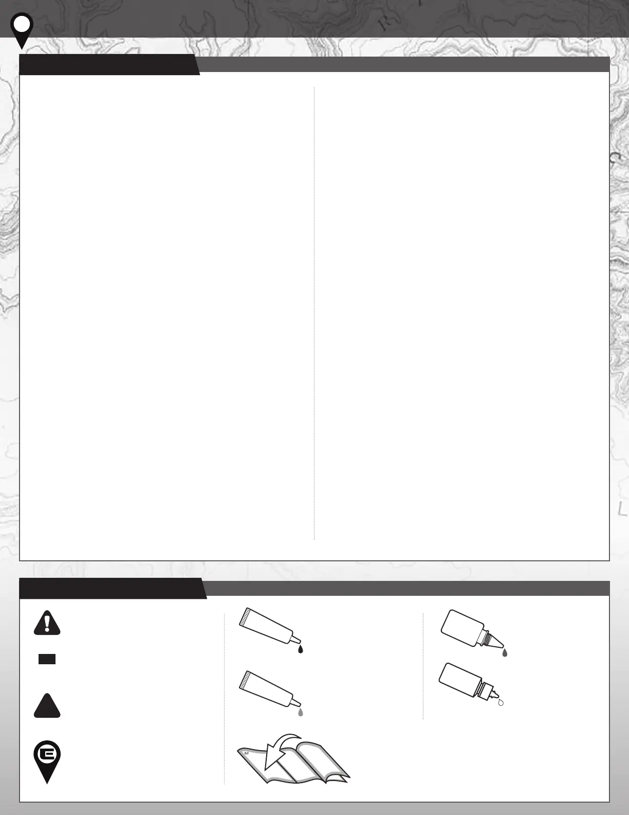
This symbol indicates
where Black Grease
should be applied.
This symbol indicates
where Shock Fluid
should be applied.
This symbol indicates the number of
the same part that is required.
This symbol indicates a Trail Tip.
2
x2
BLACK GREASE
#6588
GREEN SLIME
#1105
THREAD LOCK
#1596
SHOCK FLUID
#5422
01
COVER
02
INTRODUCTION
03
1:1 HARDWARE “FOLD OUT”
04
TABLE OF CONTENTS
05
CHASSIS BUILD
06
ELECTRONIC MOUNTS BUILD
07
GEARBOX BUILD
08
FRONT AXLES BUILD
09
REAR AXLE BUILD
09
LINKS BUILD
12
DRIVESHAFTS BUILD
13
SHOCKS BUILD
14
BODY POSTS BUILD
15
CATALOG
24
GEARBOX CONFIGURATION
25
TRAIL TIPS
26
BACK COVER
5/4/2021
This symbol indicates
where Thread Lock
Adhesive should be
applied. *not included
This symbol indicates
where Green Slime can
be applied. *not included
 Loading...