Do you have a question about the Associated Research HYPOT III 3770 and is the answer not in the manual?
Choose the correct input line voltage (115 VAC or 230 VAC) on the rear panel.
Plug the power cord into the instrument's input receptacle and a grounded power source.
Insert the Interlock Disable Key into the signal input connector to enable testing.
Switch on the instrument power and observe the initialization screen.
Connect the adapter box black lead to the CONT. CHECK terminal.
Plug the adapter box white lead into the HV output terminal.
Connect ground return lead to instrument return terminal and DUT chassis.
Connect the DUT's line cord into the adapter box receptacle.
Connect the return lead clip to the DUT's chassis or dead metal.
Connect the black ground return lead to the instrument's Return terminal.
Connect the red HV lead to the instrument's H.V. terminal and DUT conductors.
Covers exposed metal and foil-wrapped chassis connections.
Connect Interlock key, ensure DUT setup, and press TEST button to run.
Understand PASS (short beep) and FAIL (long alarm, red light) indications.
| Brand | Associated Research |
|---|---|
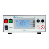
| Model | HYPOT III 3770 |
| Category | Measuring Instruments |
| Language | English |