Do you have a question about the Associated Research HYPOT III 3705 and is the answer not in the manual?
Key safety guidelines including surveying the test station, keeping unauthorized personnel away, and familiarizing with protocols.
Choose the correct input line voltage (115 VAC or 230 VAC) on the instrument's rear panel.
Connect the line power cord to the instrument and a grounded power source.
Plug the Interlock Disable Key into the signal input connector on the rear panel to enable testing.
Activate the instrument by turning the power switch to the ON position.
Navigate to and select the Test Type parameter for editing.
Use soft keys to switch between AC, DC, or IR test types.
Use arrow and soft keys to select and modify additional test parameters.
Save changes using ENTER and exit to the Perform Test screen using EXIT.
Steps for connecting the adapter box, including leads for continuity, HV output, and return.
Connect the return lead to exposed chassis metal, ground lead to the instrument, and HV lead to DUT circuitry.
Wrap non-exposed chassis in foil and connect the return lead to the foil.
Ensure the Interlock Disable Key is connected and the DUT is properly wired.
Press the green TEST button to begin the test according to Ramp and Dwell settings.
Understand PASS (audible beep, green light) and FAIL (alarm, red light) indicators.
| Test Voltage Accuracy | ± (1% of setting + 5V) |
|---|---|
| Accuracy | ± (1% of reading + 5 counts) |
| Display | LCD |
| Output Power | 500 VA |
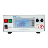
| Output Voltage (AC) | 0-5000 VAC |
| Output Voltage (DC) | 0-6000 VDC |
| Safety Standards | UL, CSA |