9
viron xt pumps Installation Manual
8
viron xt pumps Installation Manual
Section 3. Getting Started
Install the Viron XT Pump in accordance with the
procedures in this manual, local codes and ordinances,
and in accordance with the latest edition of the
appropriate national code. See Section 4.2.
This manual provides the information needed to meet
these requirements. Review all applications and
installation procedures before continuing the
installation.
3.1 Contents
Before starting, check that you have the correct parts as
indicated in Table 1. If any parts are missing or incorrect,
please call your local distributor or technical support at
1300 186 875 for assistance.
2
3
Low HighMedium
ENTER
MENU
auto
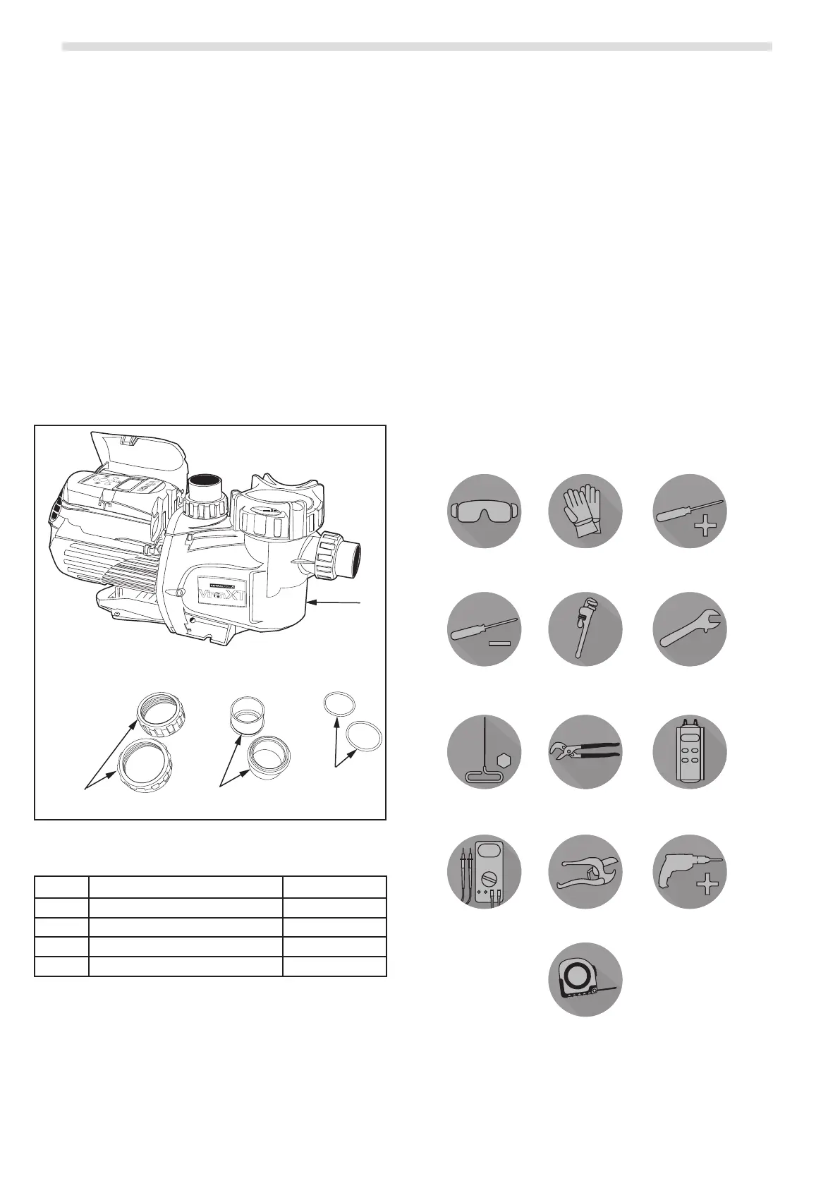
1
2*
3*
4*
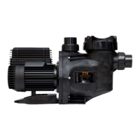
* XT pump shown with union nut, union tail and o-rings installed.
Figure 3. Viron XT Pump Components
Item Description Quantity
1 Viron XT Pump 1
2 50 mm Union Nut 2
3 50mm Universal Union Tail 2
4 50mm Universal Union O-ring 2
Table 1. XT Pump Parts
3.2 Technical Specifications
• Power: P320 XT - .75 Kw output, 240V 50 Hz, 4.1 Amp,
max speed 2850 rpm; P520 XT - 1.5 Kw output,240V
50 Hz, 6.0 amp, max speed 2820 rpm
•
25 rpm step)
•
•
•
•
•
3.3 Required Equipment
Please ensure that the following equipment is
available to the installer at the time of installation.
3.3.1 Required Tools
Safety Eye Wear
Gloves
Philips
Screwdriver
Flathead
Screwdriver
Pipe Wrench Adjustable
Wrench
5mm (3/16”)
Hex Key
Multi Grips Digital Dierential
Manometer
Voltage Meter
PVC Pipe Cutter
Tape Measure
Power Drill
Figure 4. Required Tools