Do you have a question about the AstroAI M4KOR and is the answer not in the manual?
Explains FUNC, HOLD, MAX buttons functionality for multimeter operation.
Details multimeter functions via rotary switch and FUNC button.
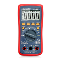
Describes purpose and connection of multimeter input/output terminals.
Covers auto shut-off, battery, and fuse replacement procedures.
Step-by-step guide for measuring AC/DC voltage with the multimeter.
Instructions for performing resistance measurements using the multimeter.
Guides for measuring capacitance and performing continuity tests.
Steps for testing diodes and determining polarity.
Guide to testing battery voltage levels using the multimeter.
How to measure AC/DC current with the multimeter.
Procedure for measuring automotive parasitic battery drain.
Instructions for using the NCV function to detect AC voltage.
Method for detecting live wires using the multimeter.
Solutions for when the multimeter reading is unstable.
Troubleshooting steps for inaccurate readings or unavailable ranges.
Steps for no reading, checking fuses, and test leads.
Details of the manufacturer's 3-year limited warranty.
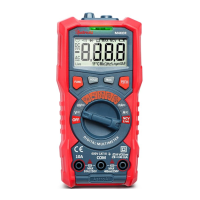
The AstroAI True RMS 4000 Count Digital Multimeter (Model M4KOR) is a battery-powered instrument designed for a wide range of electrical measurements. It features a 4000-count display and automatic ranging, making it suitable for both beginners and experienced users. The multimeter is capable of performing various tests, including AC/DC Voltage, AC/DC Current, Resistance, Capacitance, Diode Testing, Continuity Testing, NCV Detection, Live Wire Detection, and Battery Voltage Testing.
The multimeter's primary function is to accurately measure electrical parameters. It utilizes a rotary switch to select different measurement functions, and a "FUNC" button to further refine the selection when multiple applications are available within a single rotary setting. For instance, the "FUNC" button allows switching between AC and DC voltage tests or between diode and continuity tests.
For voltage measurements, the device can test both AC and DC voltages. Users connect the red test lead to the "Input" terminal and the black test lead to the "COM" terminal. The rotary dial is set to the appropriate voltage range (V= for general voltage or mV= for voltages below 400mV), and the "FUNC" button is used to select AC or DC. The LCD screen will display "DC" or "AC" to indicate the current setting. The test leads are then connected to the neutral and live wires of the circuit being measured.
Resistance measurements involve inserting the red test lead into the "Input" terminal and the black test lead into the "COM" terminal, then setting the rotary dial to the "Ω" setting. The test leads are placed at both ends of the resistance to be measured, ensuring a strong contact. The measured value is displayed on the LCD screen. The device helps determine if a resistor is functioning correctly by comparing the measured value to its nominal resistance.
For capacitance measurements, the setup is similar to resistance, with the rotary dial set to the "┫┣" setting. The "FUNC" button is pressed to switch to the Capacitance Test. A strong connection is made between the test leads and both ends of the capacitor, and the results are displayed on the LCD.
The continuity test requires de-energizing the circuit first. The test leads are connected to the "Input" and "COM" terminals, and the multimeter is set to the "•)))" position. Touching the test lead tips together should produce an audible sound, confirming proper connection. When testing an object, if the line is connected, the buzzer will beep, the indicator light will turn green, and a resistance reading will be displayed. If there is no continuity, "OL" will be displayed, and no sound will be emitted.
Diode testing involves inserting the red test lead into "Input" and the black test lead into "COM," then setting the rotary dial to the "→|" position. The "FUNC" button is used to switch to Diode Test. The red test lead is connected to the positive end of the diode (usually the longer end), and the black test lead to the negative end. The LCD will display the voltage drop across the diode.
The battery test function allows users to check 1.5V, 9V, and 12V batteries. The rotary dial is set to the corresponding battery voltage setting. The red test lead is connected to the positive electrode and the black test lead to the negative electrode. The LCD will display the battery voltage, and a red indicator light will turn on if the voltage is low.
Current measurements (AC/DC) are performed by setting the rotary dial to either "mA=" or "A=" depending on the expected current level. The "FUNC" button switches between AC and DC current functions. For "mA=" settings, the red test lead connects to the "mA" input terminal, and for "A=" settings, it connects to the "10A" terminal, with the black lead always in "COM." The power supply of the circuit under test must be disconnected, the multimeter connected in series, and then the power supply turned back on.
The Non-Contact Voltage (NCV) function detects AC voltage without the need for test leads. The rotary dial is set to the "NCV Live" position, and the NCV detector is moved close to the point to be tested. A weak AC signal will trigger a green indicator light and a slow beep, while a strong AC signal will result in a red indicator light and a quick beep.
The Live Wire Detection function also uses the "NCV Live" setting, but requires the red test lead to be inserted into the "Input" terminal (the black lead is not used). The "FUNC" button is pressed to switch to "Live" mode. Touching the point to be measured with the tip of the red test lead will trigger similar visual and audible alerts as the NCV function, indicating the presence of a live wire.
| Display | 6000 counts LCD |
|---|---|
| Continuity | Yes |
| Diode Test | Yes |
| NCV | Yes |
| Safety Rating | CAT III 600V, CAT IV 300V |
| DC Voltage | 600V |
| AC Voltage | 600V |
| DC Current | 10A |
| AC Current | 10A |
| Resistance | 60MΩ |
| Frequency | 10Hz-10MHz |
| Duty Cycle | 0.1% to 99.9% |
| Temperature Range | -40°C to 1000°C |
| Dimensions | 71mm |
| Weight | About 205g |
| Battery | 2 x AAA (included) |