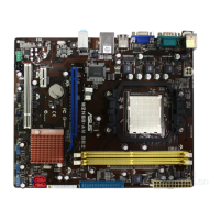
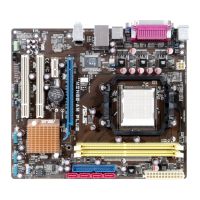
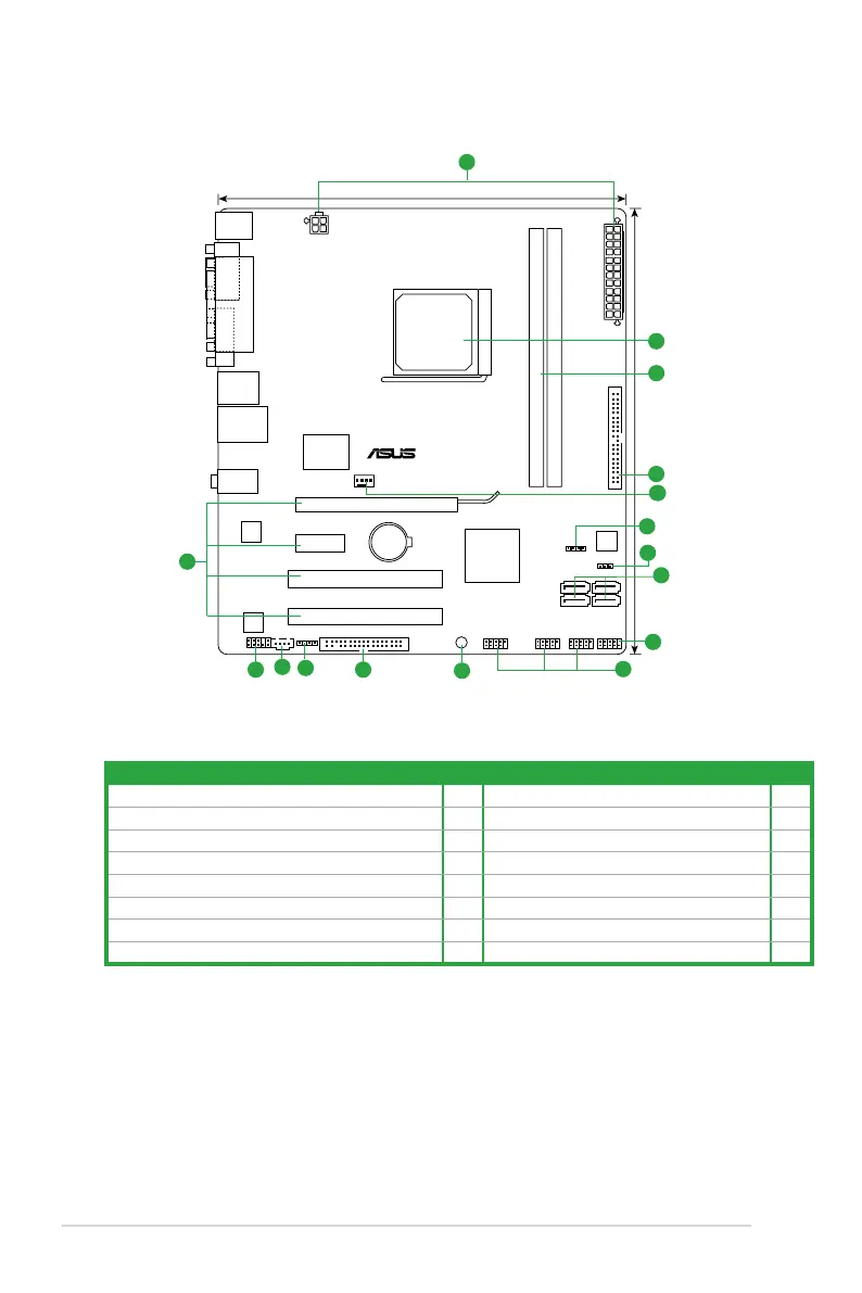
1.5.3 Motherboard layout
1.5.4 Layout contents
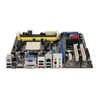
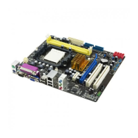
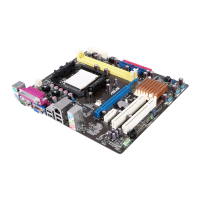
M2N68-AM
PCIEX16
PCIEX1_1
PCI2
PCI1
PRI_IDE
FLOPPY
USB56 USB78 USB910
F_PANEL
SPDIF_OUT
AAFP
CD
ATX12V
EATXPWR
CPU_FAN
Lithium Cell
CMOS Power
Super
I/O
ALC
662
RTL
8211CL
KBMS
8Mb
BIOS
SB_PWR
CLRTC
SPEAKER
22.2cm(8.75in)
24.4cm(9.6in)
Nvidia
®
MCP68
Family
DDR2 DIMM_A1 (64bit, 240-pin module)
SOCKET AM2
DDR2 DIMM_B1 (64bit, 240-pin module)
SATA2SATA1
SATA4SATA3
VGA
AUDIO
LPT
COM
LAN1_USB12
USB34
1
2
3
4
5
6
7
8
9
10
11
12
13
14
15
16
Connectors/Jumpers/Slots/LED Page Connectors/Jumpers/Slots/LED Page
1. ATX power connectors (24-pin EATXPWR, 4-pin ATX12V) 1-26 9. System panel connector (10-1 pin F_PANEL) 1-27
2. IDE connector (40-1 pin PRI_IDE)
1-21 10. Optical drive audio connector (4-pin CD) 1-24
3. CPU fan connector (4-pin CPU_FAN)
1-23 11. Front panel audio connector (10-1 pin AAFP) 1-25
4. Serial ATA connectors (7-pin SATA1, 2, 3, 4)
1-22 12. AM2 CPU Socket 1-7
5. USB connectors (10-1 pin USB56, USB 78, USB910)
1-24 13. DDR2 DIMM slots 1-10
6. Clear RTC RAM (3-pin CLRTC)
1-18 14. PCIe x16/PCIe x1/PCI slot 1-17
7. Internal speaker connector (4-pin SPEAKER)
1-25 15. Digital audio connector (4-1 pin SPDIF_OUT) 1-23
8. Standby power LED (SB_PWR)
1-4 16. Floppy disk drive connector (34-1 pin FLOPPY) 1-20
1-6 ASUS M2N68-AM
 Loading...