1-34 Chapter 1: Product introduction
9. Front panel audio connector (10-1 pin AAFP)
This connector is for a chassis-mounted front panel audio I/O module that
supports either HD Audio or legacy AC’97 audio standard.
•
We recommend that you connect a high-denition front panel audio
module to this connector to avail of the motherboard’s high-denition audio
capability.
• By default, this connector is set to HD Audio. If you want to connect a High
Denition front panel audio module to this connector, set the Front Panel
Support Type item in the BIOS to [HD Audio]. See section “2.4.4 Chipset”
for details.
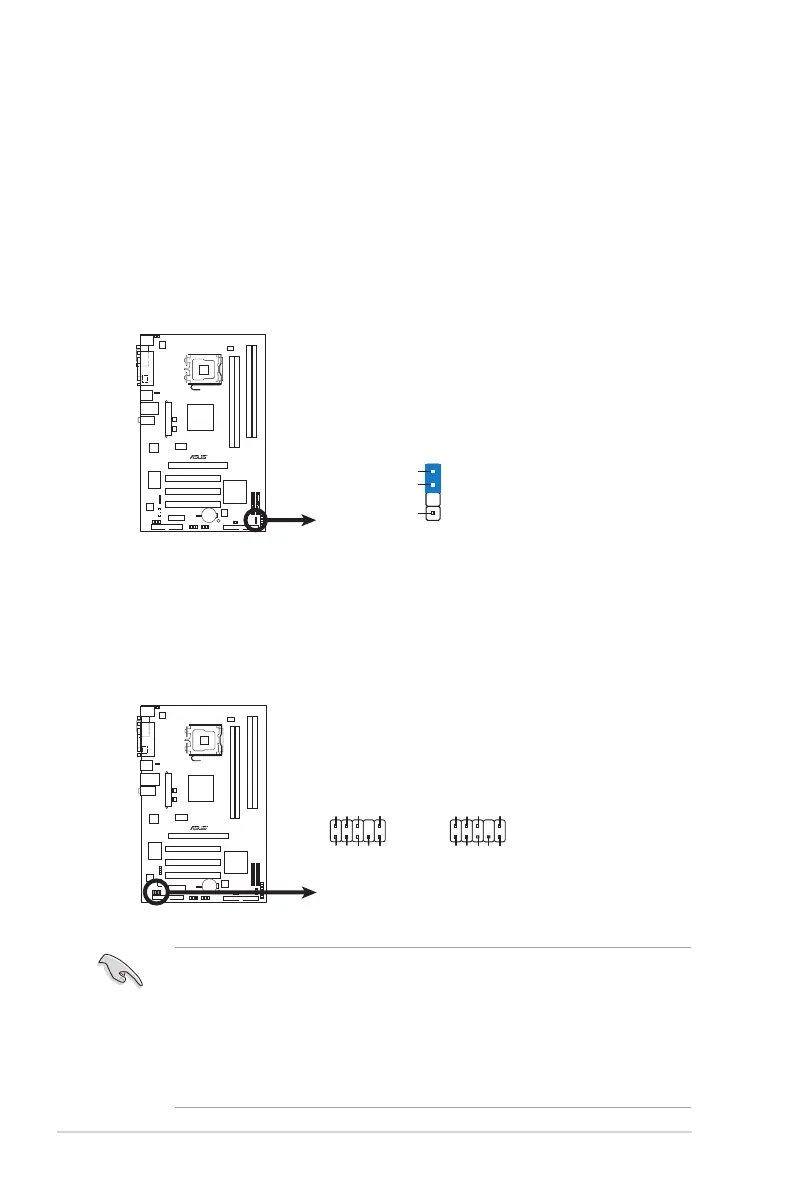
8. Chassis intrusion connector (4-1 pin CHASSIS)
This connector is for a chassis-mounted intrusion detection sensor or switch.
Connect one end of the chassis intrusion sensor or switch cable to this
connector. The chassis intrusion sensor or switch sends a high-level signal to
this connector when a chassis component is removed or replaced. The signal
is then generated as a chassis intrusion event.
By default , the pin labeled “Chassis Signal” and “ Ground” are shorted with
a jumper cap. Remove the jumper caps only when you intend to use the
chassis intrusion detection feature.