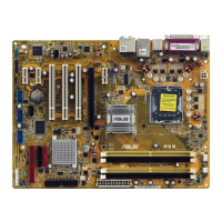
ASUS P5W 2-31
This connector does not support ATAPI devices.
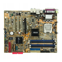
2. JMicron
®
IDE connector (40-1 pin PRI_EIDE [black])
This connector is for Ultra ATA 133/100/66 signal cables. The JMicron
®
IDE
connector supports up to two IDE hard disk drives for easier data storage.
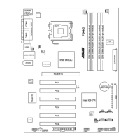
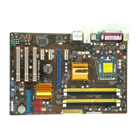
2.7.2 Internal connectors
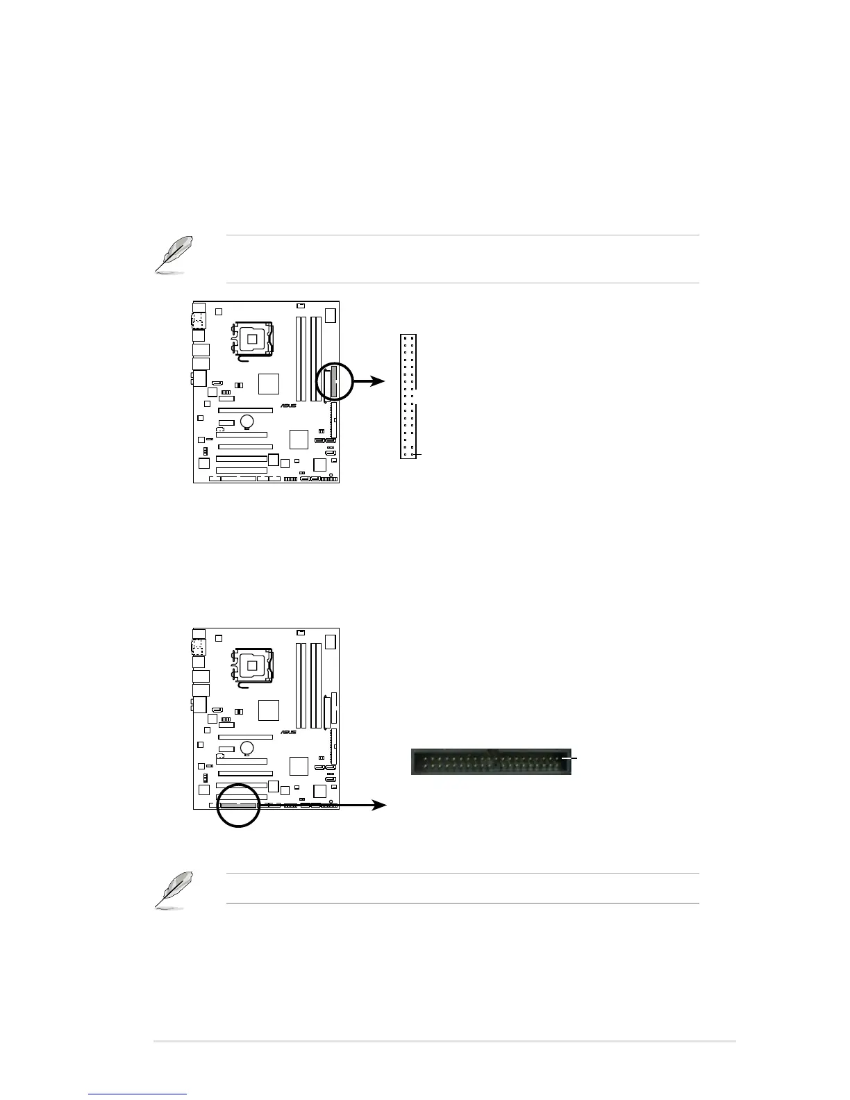
1. Floppy disk drive connector (34-1 pin FLOPPY)
This connector is for the provided oppy disk drive (FDD) signal cable. Insert
one end of the cable to this connector, then connect the other end to the
signal connector at the back of the oppy disk drive.
Pin 5 on the connector is removed to prevent incorrect cable connection when
using a FDD cable with a covered Pin 5.
P5W
®
P5W Floppy disk drive connector
NOTE: Orient the red markings on
the floppy ribbon cable to PIN 1.
PIN 1
FLOPPY
 Loading...